
Ceramic filler molding machine

A ceramic filler and molding machine technology, applied in ceramic molding machines, stone processing tools, work accessories, etc., can solve the problems of poor cutting effect and low processing efficiency, and achieve the effect of improving accuracy and efficiency, and precise automatic control.

Inactive Publication Date: 2018-12-18
李亿明
View PDF2 Cites 0 Cited by
  • Summary
  • Abstract
  • Description
  • Claims
  • Application Information

AI Technical Summary

Problems solved by technology

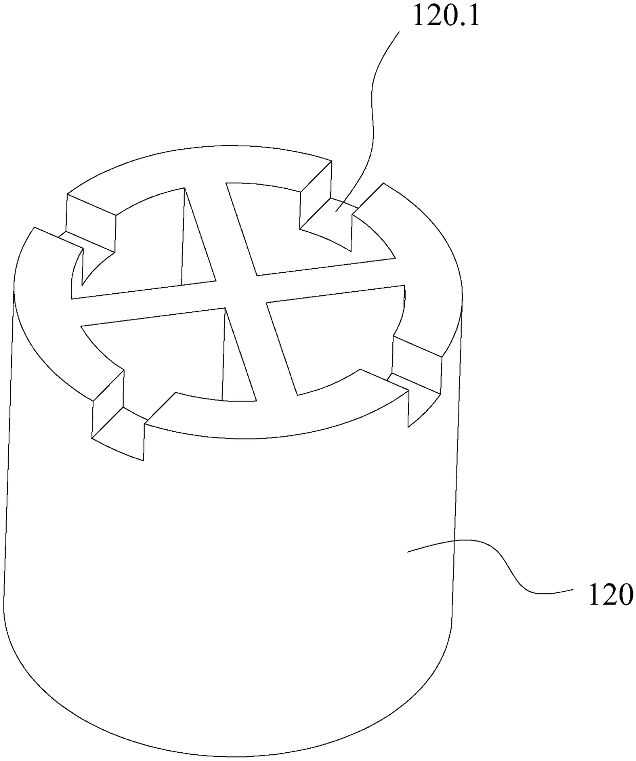
In the prior art, since there is a cross-shaped structure in the middle of the filler body 120, it has always been a difficult problem to process multiple square grooves 120.1 on its top, the processing efficiency is not high, and the cutting effect is poor

Method used


Image

  • Ceramic filler molding machine
  • Ceramic filler molding machine
  • Ceramic filler molding machine

Examples


Embodiment Construction

[0026] The present invention will be further described below in conjunction with the accompanying drawings and specific embodiments.

[0027] In the description of the present invention, it should be noted that the orientation or positional relationship indicated by the terms "directly above", "tail end", "bottom", "downward" and "lower end" are based on the orientation shown in the drawings Or positional relationship is only for the convenience of describing the present invention and simplifying the description, but does not indicate or imply that the device or element referred to must have a specific orientation, be constructed and operated in a specific orientation, and therefore should not be construed as limiting the present invention. In addition, the terms "first" and "second" are only used for descriptive purposes, for distinguishing from each other, and should not be understood as indicating or implying relative importance.

[0028] In the description of the present i...


PUM


Abstract

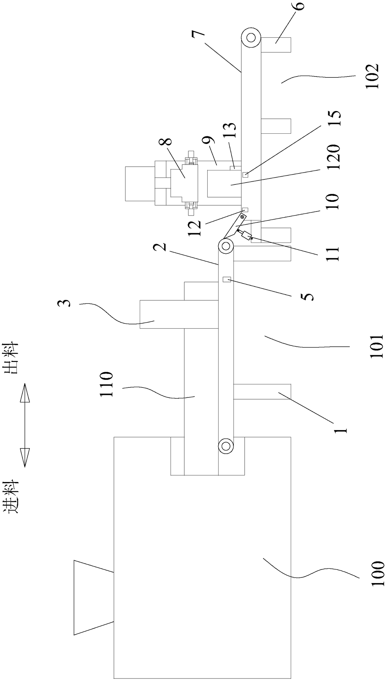
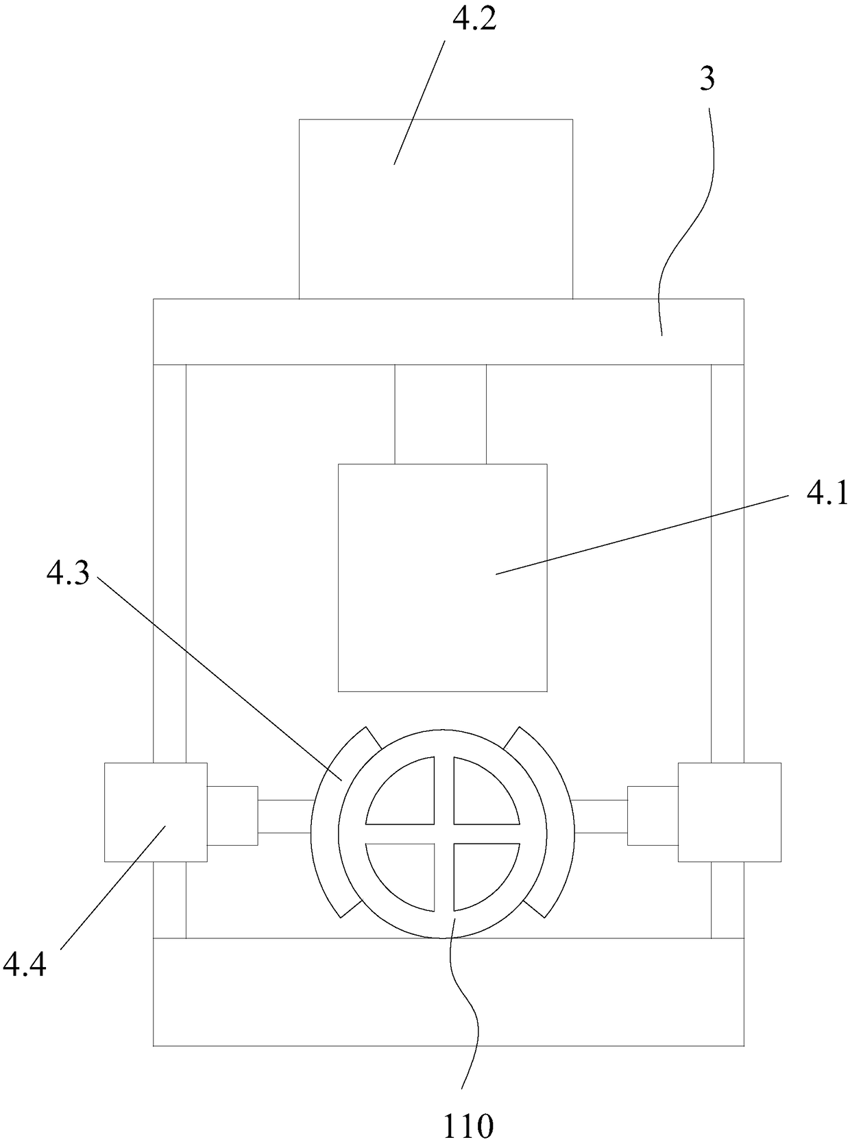
The invention discloses a ceramic filler molding machine. The ceramic filler molding machine comprises an extrusion molding machine, a cutting device and a finish machining device which are sequentially arranged side by side, wherein the cutting device comprises a first rack and a first conveyor belt; a supporting frame is arranged on the first rack; a cut-off mechanism which moves up and down isarranged on the supporting frame and used for cutting off a blank filler extruded by the extrusion molding machine; the finish machining device comprises a second rack, a second conveyor belt and at least one grooving mechanism; the grooving mechanism is used for cutting a notch positioned at the end part of a filler body being cut off; and the cut-off action and the notch cutting action are monitored and controlled through corresponding sensing control elements. By adoption of the ceramic filler molding machine disclosed by the invention, the machining process of filler cut-off and notch cutting at the end part can be automatically completed, thereby achieving the high efficiency.

Description

technical field [0001] The invention relates to the technical field of ceramic filler processing and molding, in particular to a ceramic filler molding machine. Background technique [0002] Chemical packing is the basic component of gas-liquid contact in the packed tower. It is widely used in many industries. It has excellent acid and heat resistance, and can resist the corrosion of various inorganic acids, organic acids and organic solvents except hydrofluoric acid. It can be used in It is used in various high and low occasions, and its performance is the main factor determining the operation performance of the packed tower. [0003] There are many kinds of chemical fillers, which can be divided into three categories according to the materials: ceramic fillers, plastic fillers and metal fillers. The production process of ceramic fillers requires batching, clay refining, molding and sintering, and the molding step is also very critical, which will directly affect the appea...

Claims


Application Information

Patent Timeline
IPC IPC(8): B28B3/00B28D1/22B28D7/02
CPCB28B3/00B28D1/22B28D7/02
Inventor 李亿明
Owner 李亿明
Learn More