

Logic implementation device of input clock stabilizing circuit
A technology for inputting clocks and stabilizing circuits, applied to electrical components, generating electric pulses, pulse generation, etc., can solve the problem of uncertain initial value of D flip-flop power-on, mutual deadlock of clock/reset functions, and difficulty in handling testability design And other issues
- Summary
- Abstract
- Description
- Claims
- Application Information
AI Technical Summary
Problems solved by technology
Method used
Image

Examples
Embodiment Construction
[0032] Attached below Figure 2-Figure 4 , the specific embodiment of the present invention will be further described in detail.
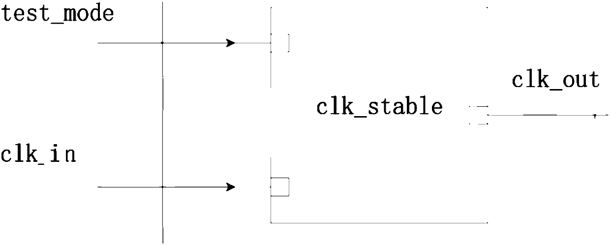
[0033] see figure 2 , figure 2 Shown is the block diagram of the logic implementation device of the input clock stabilization circuit of the present invention. Such as figure 2 As shown, the clock delay stabilization circuit module is used in digital logic circuits, which may include a test mode input terminal test_mode, a clock signal input terminal clk_in, and a clock signal output terminal clk_out. The clock delay stabilization circuit module adopted in the present invention can make the input clock of the clock signal input terminal clk_in stable after a period of time after power-on, and then the internal D flip-flop is driven by the clock signal clk_in.
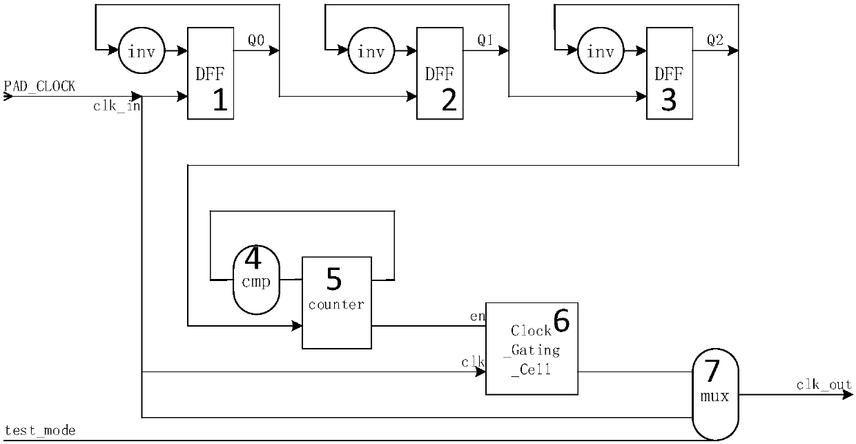
[0034] The logic implementation device of the input clock stabilization circuit is divided into four functional modules (M cascaded frequency division units, delay stabilization unit,...
PUM
 Abstract
Description
Claims
Application Information