A Logic Realization Device of Input Clock Stabilization Circuit
An input clock and stabilizing circuit technology is applied in the field of logic implementation devices of input clock stabilizing circuits, and can solve the problems of uncertain initial value of D flip-flops when power-on, difficulty in handling testability design, mutual deadlock of clock/reset functions, etc.
- Summary
- Abstract
- Description
- Claims
- Application Information
AI Technical Summary
Problems solved by technology
Method used
Image
Examples
Embodiment Construction
[0032] Attached below Figure 2-Figure 4 , the specific embodiment of the present invention will be further described in detail.
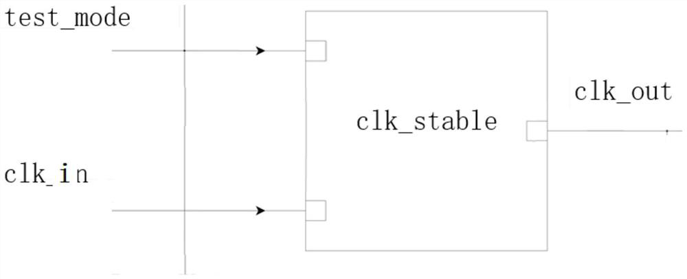
[0033] see figure 2 , figure 2 Shown is a block diagram of the logic implementation device of the input clock stabilization circuit of the present invention. Such as figure 2 As shown, the clock delay stabilization circuit module is used in a digital logic circuit, which may include a test mode input terminal test_mode, a clock signal input terminal clk_in, and a clock signal output terminal clk_out. The clock delay stabilization circuit module adopted in the present invention can make the internal D flip-flop be driven by the clock signal clk_in after the input clock of the clock signal input terminal clk_in is stabilized after a period of time after power-on.
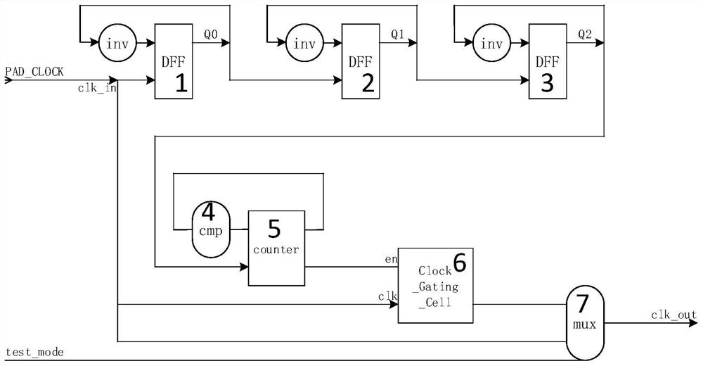
[0034] The logic implementation device of the input clock stabilization circuit is divided into four functional modules (M cascaded frequency division units, delay stabilization uni...
PUM
 Abstract
Description
Claims
Application Information
 - R&D
- Intellectual Property
- Life Sciences
- Materials
- Tech Scout
- Unparalleled Data Quality
- Higher Quality Content
- 60% Fewer Hallucinations
Browse by: Latest US Patents, China's latest patents, Technical Efficacy Thesaurus, Application Domain, Technology Topic, Popular Technical Reports.
© 2025 PatSnap. All rights reserved.Legal|Privacy policy|Modern Slavery Act Transparency Statement|Sitemap|About US| Contact US: help@patsnap.com


