Panel lock

A panel lock and panel technology, which is applied in building locks, cylinder locks, and locks with turning keys, etc., can solve the problems of poor anti-theft performance of panel locks, avoid being pried open or twisted open, and improve safety and reliability Effect

Active Publication Date: 2018-01-19
ZHUHAI UNITECH POWER TECH CO LTD
View PDF46 Cites 3 Cited by
  • Summary
  • Abstract
  • Description
  • Claims
  • Application Information

AI Technical Summary

Problems solved by technology

[0003] The main purpose of the present invention is to provide a panel lock to solve the problem of poor anti-theft performance of panel locks in the prior art

Method used


Image

  • Panel lock
  • Panel lock
  • Panel lock

Examples


Embodiment 1

[0065] The concrete unlocking process of the panel lock of embodiment one is as follows:

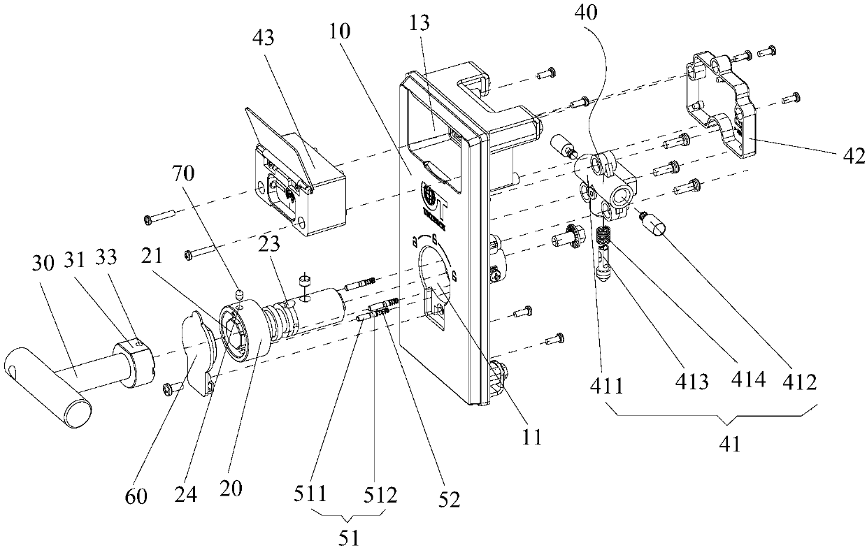
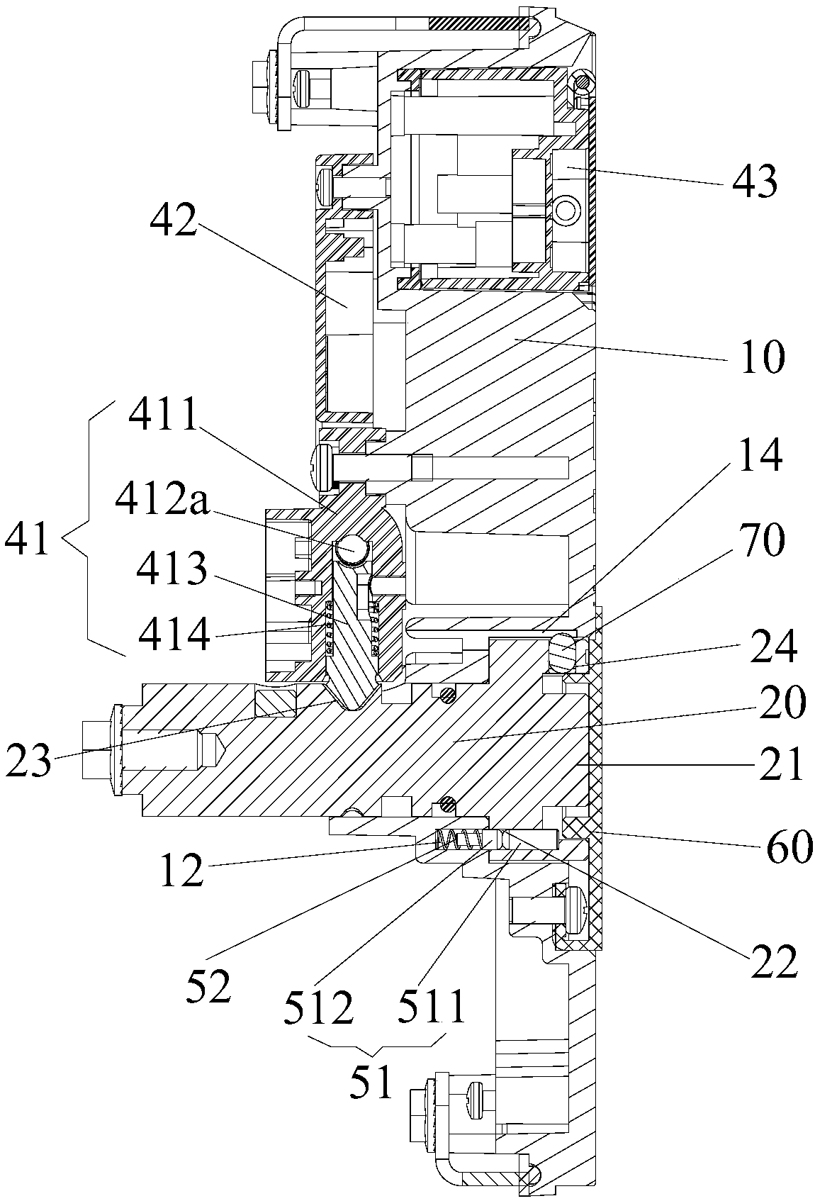
[0066] The user inserts the electronic key into the electronic key interface module 43, and when the electronic key is successfully matched with the electronic key interface module, the mandrel 412a of the control structure 412 retracts to release the restriction on the deadbolt 413, and the unlocking of the electronic locking module 40 is completed. operate. Afterwards, the user connects the handle 30 to the rotating shaft 20, and the handle 30 causes the unlocking pin 51 to release the rotating shaft 20, so that the rotating shaft 20 can rotate in the rotating shaft installation hole 11, and the user operates the handle 30 so that the handle 30 drives the rotating shaft 20 Rotate to unlock the locking structure, and then open the panel lock.

[0067] The concrete locking process of the panel lock of embodiment one is as follows:

[0068] The user rotates the handle 30 in the opposite...

Embodiment 2

[0070] The difference between the panel lock in the second embodiment and the first embodiment is that the structure of the unlocking pin 51 is different.

[0071] Optionally, the rotating shaft 20 is provided with at least one unlocking pin through hole 22 , the panel 10 is provided with at least one pin receiving hole 12 , and the rotating shaft locking mechanism includes at least one set of unlocking pins 51 . Wherein, the unlocking pin 51 is slidably installed in the unlocking pin through hole 22 and the pin accommodating hole 12, the unlocking pin 51 has a locking position and an unlocking position, the handle 30 pushes the unlocking pin 51 to move, and exits from the unlocking pin through hole 22 to the The pins are accommodated in the holes 12, so that the unlocking pins 51 can move from the locked position to the unlocked position. Such as Figure 9 and Figure 10 As shown, in the panel lock of the second embodiment, the rotating shaft locking mechanism includes thre...


PUM


Abstract

The invention provides a panel lock. The panel lock comprises a panel, a rotating shaft, a locking structure, a handle and an electronic locking module, wherein the panel is provided with a rotating shaft mounting hole; the rotating shaft is pivotally inserted in the rotating shaft mounting hole; the locking structure is in drive connection with the rotating shaft; through a pivoting motion of therotating shaft, the locking structure is enabled to be in a locking or unlocking state; the handle is detachably connected with the rotating shaft, and is rotated to enable the rotating shaft to perform the pivoting motion; the electronic locking module is arranged on the inner side of the panel, and has a locking state and an unlocking state; when the electronic locking module is in the lockingstate, the electronic locking module locks the rotating shaft, so that the rotating shaft is immobilized; and when the electronic locking module is in the unlocking state, the electronic locking module releases the rotating shaft, so that the rotating shaft can pivot relative to the rotating shaft mounting hole. The panel lock effectively solves the problem of weak antitheft performance of a panellock in the prior art.

Description

technical field [0001] The invention relates to the technical field of electric cabinet door locks for power transmission and transformation systems, and is applied to the door of an outdoor ring network cabinet. Specifically, it relates to a panel lock. Background technique [0002] Such as figure 1 As shown, in the prior art, as the supporting electric cabinet door lock of the power transmission and transformation system, the key is inserted into the panel lock 2' to unlock, the panel lock 2' releases the handle 3', and the handle 3' is turned to unlock. Yet this kind unlocking mode needs panel lock 2 ' to carry handle 3 ', and the panel lock 2 ' of carrying handle 3 ' is easy to be pried or twisted open, and anti-theft performance is bad. Contents of the invention [0003] The main purpose of the present invention is to provide a panel lock to solve the problem of poor anti-theft performance of the panel lock in the prior art. [0004] In order to achieve the above ob...

Claims


Application Information

Patent Timeline
Patent Type & Authority Applications(China)
IPC IPC(8): E05B65/02E05B3/00E05B47/00E05B27/00E05B15/14
Inventor 周子敬刘仙文琪
Owner ZHUHAI UNITECH POWER TECH CO LTD
Why Eureka
Try Eureka