
Supercritical carbon dioxide heat supply system for peak-load shifting of distributed energy resource
A distributed energy, peak-shaving and valley-filling technology, applied in heating systems, household heating, household heating, etc., can solve the problems of low efficiency, power supply coal consumption and pollutant emissions increase, so as to improve the ecological environment and increase energy Utilization efficiency, effect of improving stability
- Summary
- Abstract
- Description
- Claims
- Application Information
AI Technical Summary
Problems solved by technology
Method used
Image

Examples
Embodiment Construction
[0013] The present invention is described in further detail below in conjunction with accompanying drawing:
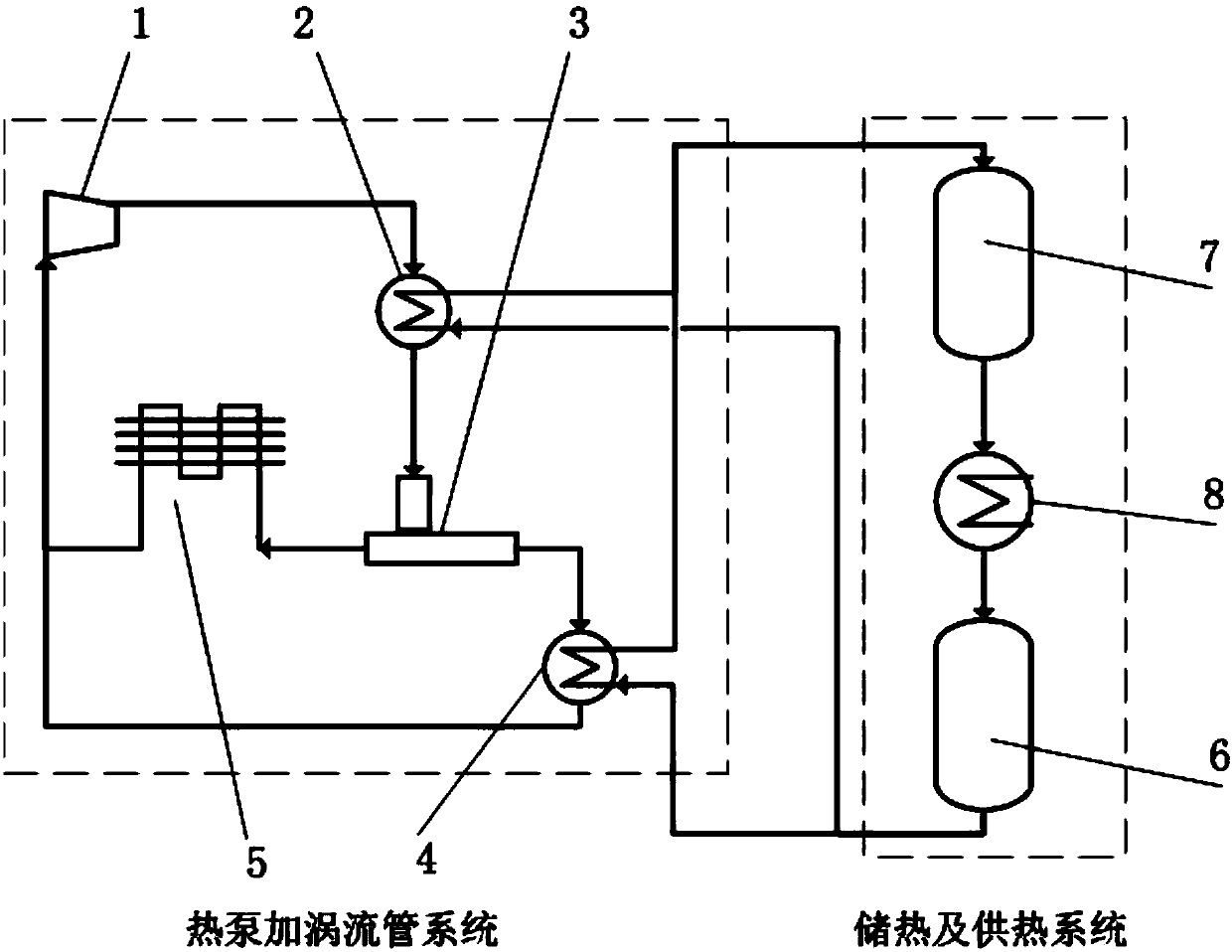
[0014] refer to figure 1 According to the present invention, a supercritical carbon dioxide heating system for distributed energy peak shaving and valley filling includes a heat pump plus vortex tube system, heat storage and heat supply system. The heat pump plus vortex tube system includes a compressor 1, a first heat storage heat exchanger 2, a vortex tube 3, a second heat storage heat exchanger 4, and a heater 5. The outlet of the compressor 1 is connected to the first heat storage heat exchanger 2. The mass side inlet is connected, the working medium side outlet of the first heat storage heat exchanger 2 is connected with the inlet of the vortex tube 3, the high temperature side outlet of the vortex tube 3 is connected with the working medium side inlet of the second heat storage heat exchanger 4, and the vortex tube The low-temperature side outlet of 3 is connect...
PUM
 Abstract
Description
Claims
Application Information