Novel flat television antenna

A flat-panel TV and antenna technology, applied in the direction of the antenna support/installation device, etc., can solve the problems of inconvenient use, poor signal reception, inconvenient installation, etc., and achieve the effects of wide application, improved efficiency and simple structure

Pending Publication Date: 2018-01-19
SHENZHEN ANTOP TECH +1
View PDF0 Cites 2 Cited by
  • Summary
  • Abstract
  • Description
  • Claims
  • Application Information

AI Technical Summary

Problems solved by technology

The hanging method needs to drill holes on the wall. This method is not applicable when there is no background wall or the background wall is not suitable for drilling or there is no background wall, and there are many inconveniences in installation.
For the method of placing under the flat-panel TV through the support, the flat-panel antenna is affected by the radiation of the flat-panel TV, the signal reception is poor, and it takes up a lot of space, which is not easy to use

Method used


Image

  • Novel flat television antenna
  • Novel flat television antenna
  • Novel flat television antenna

Examples


Embodiment 1

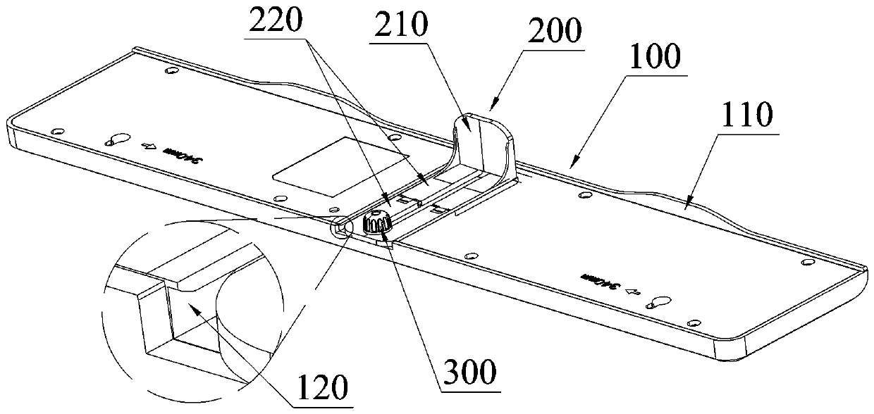
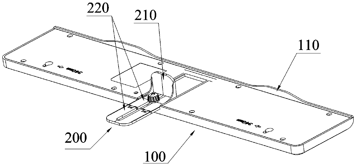
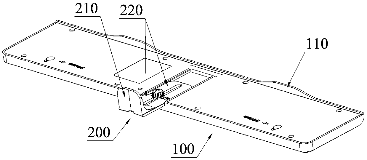
[0035] Such as figure 1 As shown, a new type of flat-panel TV antenna is erected on the top of the flat-panel TV, and includes a strip-shaped host 100, a bracket 200 and a locking mechanism 300. The front edge of the host 100 is provided with a front support plate 110, and the lower side is provided with a Guide slot 120, the bracket 200 includes a rear support plate 210 and an adjustment plate 220 that are connected to each other and intersect with each other, the adjustment plate 220 cooperates with the guide slot 120 and is fixedly connected with the host 100 through a locking mechanism 300, the The front support plate 110 cooperates with the rear support plate 210 to clamp the flat-screen TV. When assembling the antenna, it can be installed in two ways: forward installation or reverse installation. Forward installation: such as figure 2 As shown, the rear support plate 210 is located between the front support plate 110 and the adjustment plate 220; reverse installation: ...

Embodiment 2

[0040] The difference between this embodiment and embodiment 1 is: as Figure 6 As shown, the first hinged part 2211 is provided on the rear side of the first folding plate 221, and the second hinged part 2221 is provided on the front side of the second folding plate 222, and the first hinged part 2211 is connected to the second hinged part. The parts 2221 are hinged to each other, the left side and / or right side of the first hinged part or the second hinged part are provided with protrusions, and the left side and / or right side of the second hinged part or the first hinged part are provided with Groove, when the first folding board and the second folding board are turned over to the same plane, the protrusion and the groove are interlocked, and the cooperation between the protrusion and the groove can effectively prevent the first folding board or the second folding board from being free. Flip, just apply force to make it flip when it needs to flip.

Embodiment 3

[0042] The difference between this embodiment and embodiment 1 is: as Figure 7~8 As shown, the first hinged part 2211 is provided on the rear side of the first folding plate 221, and the second hinged part 2221 is provided on the front side of the second folding plate 222, and the first hinged part 2211 is connected to the second hinged part. The parts 2221 are hinged to each other, and the angle between the rear side and the upper side of the first hinged part 2211 and / or the angle between the front side and the upper side of the second hinged part 2221 is a right angle, avoiding the first folding plate 221 is turned upwards to ensure the effective cooperation between the rear support plate 210 and the front support plate 110, so that the antenna can be stably erected on the top of the flat-panel TV; the angle between the rear side and the upper side of the first hinge part 2211 and the described The included angle between the front side and the upper side of the second hing...


PUM


Abstract

The invention relates to the field of television antennas and discloses a novel flat television antenna. The novel flat television antenna is arranged at the top of a flat television and comprises a strip host, a bracket and a lock mechanism, wherein a front support plate is arranged on the front edge of the host and a guide slot is formed in the lower side; the bracket comprises a rear support plate and an adjusting plate which are connected with each other and are arranged in an intersecting manner; the adjusting plate is matched with the guide slot and fixedly connected with the host through the lock mechanism; and the front support plate is matched with the rear support plate to clamp the flat television. The guide slot is formed in the lower side of the host, and the adjusting plate arranged on the bracket is connected with the guide slot in a sliding manner, so that other five degrees of freedom between the bracket and the host are limited and the installation efficiency is greatly improved.

Description

technical field [0001] The present invention relates to the field of television antennas, and more specifically, relates to a novel flat-panel television antenna. Background technique [0002] With the widespread use of flat-panel TVs, antennas suitable for flat-panel TVs are also developed. The current flat-panel TV antennas mainly have two types: outdoor and indoor. For the indoor antenna structure suitable for flat-panel TVs, the flat-panel antennas are mainly used. Flat-panel TVs are divided into plate-type structures and strip-shaped structures. On the top of the flat-panel TV, but the signal receiving area is small, the signal receiving effect is poor, and the signal optimization needs to be adjusted through angle adjustment, which increases the complexity of its installation structure. The strip-shaped structure has a large volume and good signal reception effect, but it takes up a lot of space and it is not easy to choose the location. Generally, the strip-shaped f...

Claims


Application Information

Patent Timeline
Patent Type & Authority Applications(China)
IPC IPC(8): H01Q1/12H01Q1/22
Inventor 杨瑞典
Owner SHENZHEN ANTOP TECH
Why Eureka
Try Eureka