Aluminum alloy in-opening window

A technology of inward opening windows and aluminum alloys, which is applied in the direction of windows/doors, window glass installation, building components, etc., can solve problems such as the influence of building thermal insulation performance, energy saving and emission reduction obstacles of houses, etc., to increase thermal insulation performance and Sealing performance, material saving, and strong versatility

Inactive Publication Date: 2018-01-26
HENAN HENGMEI ALUMINUM
4 Cites 0 Cited by

AI-Extracted Technical Summary

Problems solved by technology

Most of the existing aluminum alloy inward opening windows are composed of operating elements including frame, fixed fan, inner opening fan, and middle stiles. Due to the good thermal conductivity of aluminum alloy, the heat conduction between indoors and outdoors is rapid, ...

Method used

As shown in Figure 8, isobaric rubber strip 9 comprises body 901 and contact lip 902, is provided with cavity 904 in body 901, and body 901 both sides are respectively provided with the first groove that is connected with frame or middle stile and The second groove; a raised portion 904 is provided on the body 901 . The contact lip 902 is arranged on the body 901. The contact lip 902 is curved. The contact lip 902 forms a closed hollow cavity with the body 901. The body 901 is made of EPDM material, and the contact lip 902 is honeycomb-shaped. rubber material. The contact lip 902 of this embodiment adopts a curved arc shape, and the point contact between the contact lip 902 and the heat-insulating bridge is changed from the conventional point contact to the surface contact of the present invention, which improves the sealing effect and reduces the difficulty of construction.
Inwardly opening the outside profile of the fan room and including the lower joint surface 206, the lower support body 207 and the lower edge 209, the lower joint surface 206 is provided with two left heat insulation bridges 205 and the right insulation bridge with the inner fan frame heat insulation bridge. The end of the thermal bridge 211 is wedge-shaped to match two wedge-shaped grooves, the lower support body 207 is arranged between the lower joint surface 206 and the lower bottom edge 209, the cross section of the lower support body 207 is square, and the bottom of the lower support body 207 is provided with a lower bottom side 209, one end of the lower bottom edge 209 is provided with a first groove 210 for installing a glass sealing strip, and the side of the lower bottom edge 209 close to the lower joint surface 206 is an inclined surface 208, and the setting of the inclined surface 208 increases the thickness of the lower bottom edge 209. The strength of the profile is not easy to deform after long-term use. The profile inside the inner-opening fan room includes an upper joint surface 204, an upper support body 203, and an upper bottom edge 201. On the upper joint surface 204, two left heat-insulation bridges 205 and right heat-insulation bridges 211 are arranged on the inner-opening frame heat-insulation bridge. Two wedge-shaped grooves matching the wedge shape of the end of the cross-section, the upper support body 203 is arranged between the upper joint surface 204 and the upper bottom edge 201, one end of the upper bottom edge 201 is provided with a second groove 202, and the upper support body 203 on both sides ...

Abstract

The invention provides an aluminum alloy in-opening window. An in-opening fan is arranged in an edge frame. The in-opening fan includes an in-opening fan frame, in-opening fan glass and an in-openingfan pressing line. The in-opening fan glass is of a three layers of glass structure. The edge frame and the in-opening fan frame are each of a divided structure. An edge frame heat insulation bridge and an in-opening fan frame insulation bridge are formed in the middle of the section of each of the edge frame and the in-opening fan frame through a heat insulating element in sequence correspondingly. The edge frame heat insulation bridge and the in-opening fan frame insulation bridge are located between inner glass and outer glass of the in-opening fan glass to form an isothermal layer. The outdoor side bottom edges of the in-opening fan frame and the edge frame are on the same horizontal plane. The edge frame includes an edge frame outdoor side aluminum profile, an edge frame heat insulation bridge and an edge frame indoor side aluminum profile. A frame corner connector is arranged in a cavity of the edge frame outdoor side aluminum profile. The two sides of the frame corner connectorare each provided with a guide plate which is matched with the frame corner connector. According to the aluminum alloy in-opening window, the heat insulation performance and the sealing performance ofthe aluminum alloy in-opening window are improved, materials are saved, the profiles are high in generality, and installing and using are convenient.

Application Domain

Sealing arrangementsWing arrangements +1

Technology Topic

EngineeringDivided structure +2

Image

  • Aluminum alloy in-opening window
  • Aluminum alloy in-opening window
  • Aluminum alloy in-opening window

Examples

  • Experimental program(1)

Example Embodiment

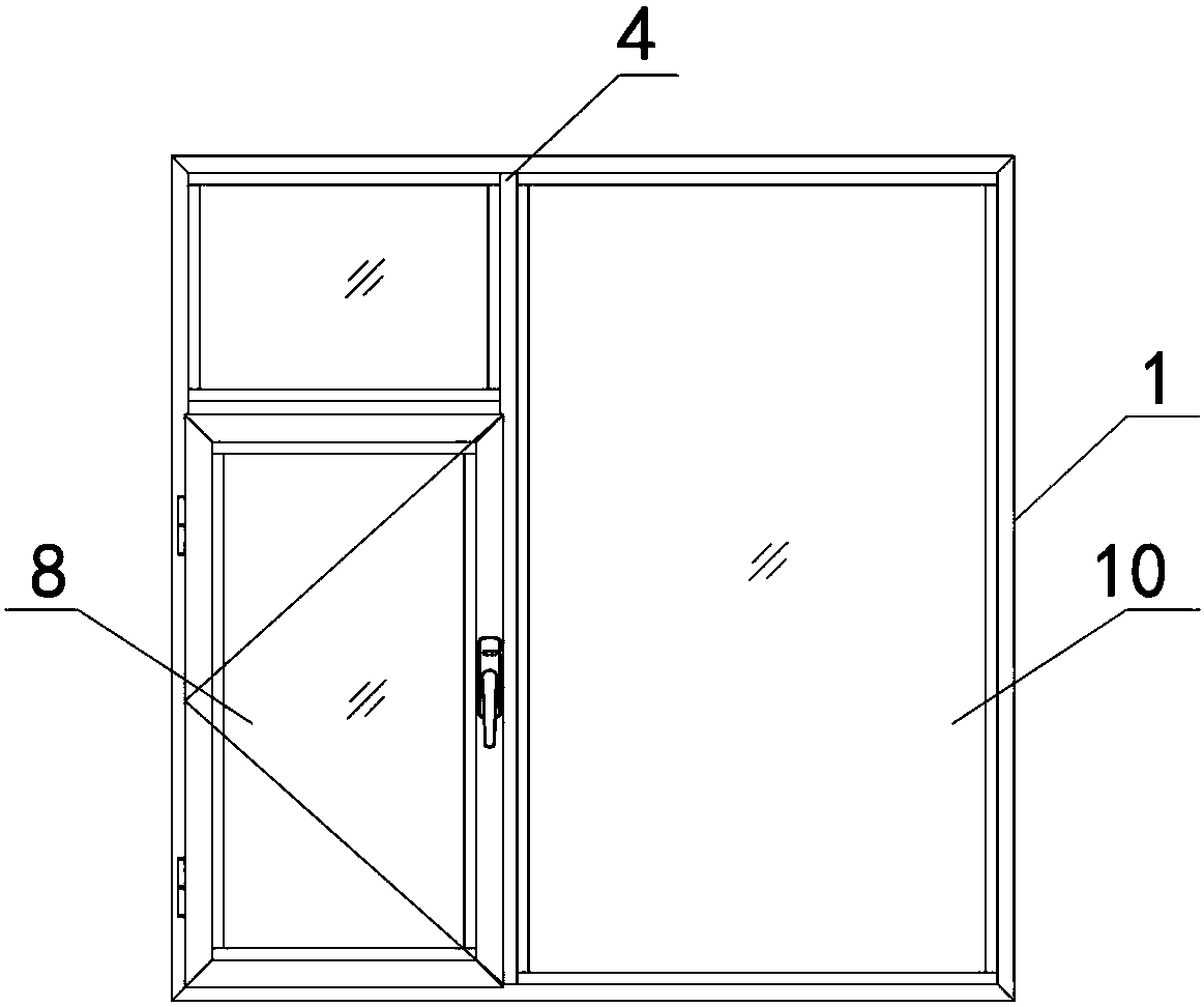
[0041] Such as figure 1 , figure 2 As shown, the present invention provides an aluminum alloy inner opening window, which includes a frame 1, an inner opening fan is arranged in the frame 1, and the inner opening fan includes an inner opening fan frame 2, an inner opening glass 8 and an inner opening fan pressing line 3. The opening glass 8 is arranged on the inner opening frame 2 via the inner opening pressing line 3. The inner fan glass 8 is a three-layer glass structure; the frame 1 and the inner fan frame 2 are all split structures, and the middle part of the cross section is formed by heat insulating elements to form a frame heat insulation bridge and an inner fan frame heat insulation bridge. The heat insulation bridge and the inner opening fan frame heat insulation bridge are located between the inner glass and the outer glass of the inner opening fan glass to form an isothermal layer.
[0042] The exterior of the inner opening fan of the inner opening window in the prior art has a protruding edge. The overall flatness of the inner opening fan affects the tightness of the combination between the outer edge of the inner opening fan and the window frame, resulting in the outer edge of the inner opening fan There is a gap between the window frame and the window frame. When the wind blows or there is dust or fine dust (PM2.5) that touches the joint between the inner opening fan and the window frame, it will enter the room along the gap or stay in the gap. Affect the sealing performance of windows. The inner opening fan frame 2 of the present invention is on the same horizontal plane as the outdoor bottom side of the frame 1. When the inner opening fan 2 is closed, the glass outer waterproof composite rubber strip 6 on the inner opening fan is pressed against the inner opening fan frame. At the same time, a sealing rubber strip is arranged at the gap formed between the bottom edge 107 of the frame and the bottom bottom edge 2095 of the inwardly-opened fan frame to realize double sealing guarantee. This avoids that in the prior art, since the bottom edge 107 of the frame and the bottom bottom edge 209 of the inward-opening fan frame have different heights, dust, rain, etc. are likely to enter the window from the side.
[0043] A middle stile 4 is also arranged in the frame 1, and a fixed fan is arranged between the middle stile 4 and the frame 1. The fixed fan includes a fixed fan pressing line 5 and a fixed fan glass 10, and the fixed fan glass 10 is respectively set on the fixed fan pressing line 5 On the middle stile 4 and the frame 1; the middle stile 4 is a split structure, the middle of the middle stile 4 is provided with a heat insulating element to form a middle stile insulation bridge, the middle stile insulation bridge and the frame insulation bridge, and the inner fan insulation bridge In the same plane. The fixed fan glass 10 and the inward fan glass 8 are arranged horizontally and parallel.
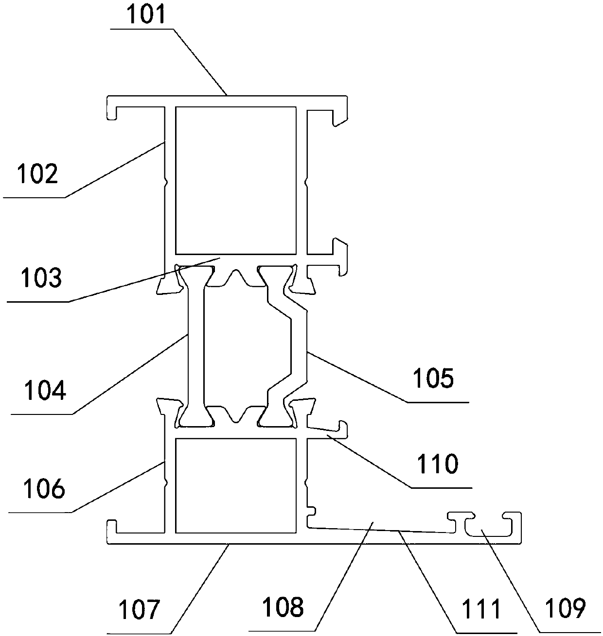
[0044] Such as image 3 As shown, the frame includes the outdoor side aluminum profile of the frame, the frame heat insulation bridge and the frame indoor side aluminum profile. The frame outdoor side aluminum profile and the frame indoor side aluminum profile are split structures, and the frame heat insulation bridge is set on the frame outdoor side aluminum profile and Between the aluminum profiles on the indoor side of the frame; the aluminum profiles on the outdoor side of the frame and the aluminum profiles on the indoor side of the frame are both hollow square cavities. The frame insulation bridge includes a left insulation bridge 104 and a right insulation bridge 105. The left thermal insulation bridge 104 is an I-shaped thermal insulation strip, and the right thermal insulation bridge 105 is a C-shaped thermal insulation strip.
[0045] The aluminum profile on the outdoor side of the frame is located on the outdoor side of the frame, and includes a bottom edge 107, a support body 106, and a joining surface 110. The support body 106 is disposed between the bottom edge 107 and the joining surface 110. The bottom edge 107 is located on the outdoor side surface and is straight. One end is provided with a slot 108 for installing the angle steel sheet 12 and a groove 109 for installing the glass outer waterproof composite rubber strip, between the support 106 and the groove 109 On the bottom side of the, the side close to the joint surface is an inclined surface 111, that is, the bottom of the card slot 108 is an inclined surface. The inclined surface increases the strength of the profile and is not easy to deform. The aluminum profile on the outdoor side of the frame is a hollow square cavity 11 with a frame corner code 1101 in the cavity; the joint surface 110 is set on the support 106, and there are two wedge-shaped grooves. The size and shape of the wedge-shaped groove are respectively the same as those of the left insulation bridge 104 It matches with the wedge-shaped structure at the end of the right heat-insulating bridge 105; both ends of the left heat-insulating bridge 104 and the right heat-insulating bridge 105 are respectively provided with wedge-shaped structures. The indoor side aluminum profile of the frame includes an upper bottom edge 101, an upper support body 102, and an upper joint surface 103; the upper bottom side 101 is located on the indoor side surface of the frame aluminum profile; the upper support body 102 is arranged on the upper bottom edge 101; the upper support body 102 is provided with a card slot on one side; the upper joint surface 103 is provided on the upper support body 102, and the upper joint surface 103 is provided with a position corresponding to the joint surface of the aluminum profile outside the frame Two wedge-shaped grooves, the size and shape of the wedge-shaped grooves are matched with the wedge-shaped structure of the cross-sectional ends of the left heat-insulating bridge 104 and the right heat-insulating bridge 105 respectively; the bonding surface of the aluminum profile on the outdoor side of the frame and the aluminum on the 110 frame indoor The upper joint surface 103 of the profile forms a groove for installing the iso-pressure adhesive strip, and the iso-pressure adhesive strip is arranged on one side of the C-shaped heat insulation strip.
[0046] The distance from the outer surface of the bottom side of the outdoor aluminum profile of the frame to the bottom of the wedge groove of the joint surface is equal to the distance from the outdoor surface of the outdoor aluminum profile in the same direction of the middle stile and the inner open fan frame to the bottom of the wedge groove of the joint surface. The cross-section heights of the left heat-insulating bridge 104 and the right heat-insulating bridge 105 are equal, and are equal to the cross-section heights of the heat-insulating bridges on the middle stile aluminum profile and the inner fan frame aluminum profile.
[0047] Such as Figure 4 As shown, the inner open fan frame 2 includes an inner open fan outdoor side profile, an inner open fan indoor side profile, and an inner open fan frame heat insulation bridge. The inner open fan frame heat insulation bridge is provided with the inner open fan outdoor profile and the inner open fan Between the indoor side profiles, the outdoor side profiles of the inner open fan and the indoor side profiles of the inner open fan are all hollow square cavities. The heat-insulating bridge of the inner open fan frame includes a left heat-insulating bridge 205 and a right heat-insulating bridge 211; the right heat-insulating bridge 211 is a C-shaped heat-insulating strip; the left heat-insulating bridge 205 is a CT-shaped heat-insulating strip. The strip includes a C-shaped insulation strip and an L-shaped insulation strip arranged in the middle of the C-shaped insulation strip. One end of the horizontal part of the L-shaped insulation strip is set on the C-shaped insulation strip, and the other end is connected to the L-shaped insulation strip. Inclined part; the inclined part of the L-shaped heat insulation strip is in contact with the isobar 9.
[0048] The exterior side profile of the inner open fan includes a lower joint surface 206, a lower support body 207 and a lower bottom edge 209. The lower joint surface 206 is provided with two left insulation bridges 205 and right insulation bridges 211 which are insulated with the inner open fan frame. Two wedge-shaped grooves matching the wedge shape of the end of the lower support body 207 are arranged between the lower joint surface 206 and the lower bottom side 209. The cross section of the lower support body 207 is square, and the bottom of the lower support body 207 is provided with a lower bottom side 209. One end of the lower bottom side 209 is provided with a first groove 210 for installing a glass sealing strip, and the side of the lower bottom side 209 close to the lower joint surface 206 is an inclined surface 208. The provision of the inclined surface 208 increases the profile strength of the lower bottom side 209. It is not easy to deform after regular use. The interior side profile of the inner open fan includes an upper joint surface 204, an upper support body 203 and an upper bottom edge 201. The upper joint surface 204 is provided with two left insulation bridges 205 and right insulation bridges 211 which are insulated with the inner open fan frame. Two wedge-shaped grooves with matching wedge-shaped cross-section ends, the upper support 203 is arranged between the upper joining surface 204 and the upper bottom 201, one end of the upper bottom 201 is provided with a second groove 202, on both sides of the upper support 203 The third groove 203 and the fourth groove 204 are respectively provided. The side of the upper bottom 201 close to the outdoor is a slope, which increases the profile strength of the upper bottom 201.
[0049] Such as Figure 5 As shown, the middle stile 4 includes a middle stile indoor side profile, a middle stile insulation bridge, and a middle stile outdoor side profile. The outdoor side profile of the stile is located on the outdoor side of the stile and includes a bottom side 408, a support body 407 and a joint surface 406. The support body 407 is arranged between the bottom side 408 and the joint surface 406; the bottom side 408 is located on the outdoor side surface, It is a straight type. One end is provided with a first groove for installing a glass outer waterproof composite rubber strip 6, and the other end is provided with a second groove 42 for installing a glass sealing strip. The bottom side 411 near the joint surface is an inclined surface. The bonding surface 406 is set on the support 407 and has two wedge-shaped grooves, the size and shape of the wedge-shaped grooves are matched with the wedge-shaped structures at the ends of the left and right insulation bridges 404 and 405 respectively. Both ends of the left insulation bridge 404 and the right insulation bridge 405 are respectively provided with wedge-shaped structures. The indoor side aluminum profile of the middle stile includes an upper bottom 401, an upper support 402, and an upper joint surface 403; the upper bottom 401 is located on the indoor side surface of the middle stile; the upper support 402 is set on the upper bottom 401; Grooves are provided on both sides of the support body 402; the upper joint surface 403 is provided on the upper support body 402, and the upper joint surface 403 is provided with two wedge-shaped grooves corresponding to the position of the joint surface of the aluminum profile outside the central stile. The size and shape of the groove are matched with the wedge-shaped structure of the cross-sectional ends of the left and right insulation bridges 404 and 405 respectively; between the joint surface 406 of the aluminum profile on the outside of the middle stile and the upper joint surface 403 of the aluminum profile on the inside of the middle stile A groove for installing the isobar 9 is formed in between, and the isobar 9 is arranged on one side of the C-shaped insulation bar.
[0050] Such as Image 6 As shown, the fixed fan pressing line 5 includes a bent part, a curved part 503 and a rib 504. The bent part includes a straight part 502 and a bent part 501. The bent part 501 of the bent part is connected to the stile or frame , The straight part 502 is connected with the rib 504, the one side of the curved part 503 is connected with the stile or the frame, and the other side is connected with the rib 504. The rib 504 is provided with a groove for installing a glass sealing strip.
[0051] In one embodiment, the inward fan pressing line 3 can also adopt the same structure as the fixed fan pressing line 5. The inward fan pressing line 3 includes a bent part, a curved arc part and a rib. The open fan frame is connected, the other side is connected with the rib, one side of the curved arc part is connected with the inner open fan frame, and the other side is connected with the rib. A groove for installing a glass sealing strip is provided on the rib.
[0052] Such as Figure 7 As shown, the glass outer waterproof composite rubber strip 6 includes a lip 603 and a skeleton 601. The skeleton 601 is provided with a wedge-shaped part matching the first groove of the frame, and the middle part of the skeleton is a hollow cavity 602. The lip 603 is arranged at one end of the skeleton, and the lip is straight. The skeleton 601 is an EPDM rubber skeleton, and the lip 603 is a honeycomb rubber lip.
[0053] Such as Figure 8 As shown, the isobaric rubber strip 9 includes a body 901 and a contact lip 902. The body 901 is provided with a cavity 904, and both sides of the body 901 are respectively provided with a first groove and a second groove connected to the frame or the stile; A protrusion 904 is provided on the main body 901. The contact lip 902 is arranged on the body 901, the contact lip 902 is curved, the contact lip 902 and the body 901 form a closed hollow cavity, the body 901 is made of EPDM rubber, and the contact lip 902 is of honeycomb shape Rubber material. The contact lip 902 of this embodiment adopts a curved arc shape, and the contact lip 902 and the thermal insulation bridge change from the previous point contact to the surface contact of the present invention, which increases the sealing effect and reduces the difficulty of construction.
[0054] Such as figure 2 As shown, the three-layer glass of the fixed fan glass 10 and the inner fan glass 8 are arranged in parallel and equidistant, and the two adjacent layers of glass are sealed with a glass inner sealing tape 7; the glass inner sealing tape 7 includes EPDM The rubber strip and the honeycomb rubber strip are arranged on the inner side, and the EPDM rubber strip is arranged on the outer side.
[0055] Such as Picture 9 As shown, the group angle steel sheet 12 is V-shaped and includes a first side wing 1201 and a second side wing 1202. The first side wing 1201 and the second side wing 1202 are provided with a first groove 1205 on the joint surface, and the first groove 1205 is provided with an injection In the glue hole 1206, a second groove 1203 and a third groove 1204 are respectively provided on the first side wing and the second side wing. An arc-shaped notch 1207 is provided at one end of the first side wing 1201 and the second side wing 1202 close to the second groove 1203 and the third groove 1204. In one embodiment, the second groove 1203 and the third groove 1204 are both rhomboid.
[0056] Such as Picture 10 , Picture 11 As shown, the frame corner code 1101 is set in the hollow square cavity of the aluminum profile inside the frame of the frame profile, and both sides of the frame corner code 1101 are provided with baffles matching the frame corner code. The deflector includes a deflector body 1102, and the deflector body is L-shaped. The two ends of the L-shaped deflector are provided with a first connecting portion 1103 and a second connecting portion 1105, respectively, the middle of the deflector is provided with a third connecting portion 1106, and both sides of the third connecting portion 1106 are respectively provided with first drainage grooves 1104 and 1105. The second drainage groove 1107.
[0057] The above descriptions are only preferred embodiments of the present invention and are not intended to limit the present invention. Any modification, equivalent replacement, improvement, etc. made within the spirit and principle of the present invention shall be included in the protection of the present invention. Within range.

PUM

no PUM

Description & Claims & Application Information

We can also present the details of the Description, Claims and Application information to help users get a comprehensive understanding of the technical details of the patent, such as background art, summary of invention, brief description of drawings, description of embodiments, and other original content. On the other hand, users can also determine the specific scope of protection of the technology through the list of claims; as well as understand the changes in the life cycle of the technology with the presentation of the patent timeline. Login to view more.

Similar technology patents

Aluminum alloy inward-opening window

InactiveCN107605332AIncrease thermal insulation performance and sealing performancesave material
Owner:HENAN HENGMEI ALUMINUM

Union type single tube pass floating head heat exchanger

ActiveCN105823352AThe structure of the floating head is simplesave material
Owner:SINOPEC ENG +1

Tube punching and collaring system, device and method

InactiveUS20080163662A1save materialreliable strength
Owner:DAGAN MOSHE

Aluminum alloy outwards-opening window

InactiveCN107476714AIncrease thermal insulation performance and sealing performancesave material
Owner:HENAN HENGMEI ALUMINUM

Prefabricated assembled type upright post connecting structure and construction method thereof

PendingCN108457192Asave materialReduce weakening and stress effects
Owner:SHANGHAI MUNICIPAL ENG DESIGN INST GRP

Classification and recommendation of technical efficacy words

  • save material
  • Increase thermal insulation performance and sealing performance

Plastic film

InactiveUS20140079938A1save materiallow density
Owner:MONDI CONSUMER PACKAGING TECH

Micro USB (universal serial bus) receptacle

Owner:ZHONGSHAN K MATE GENERAL ELECTRONICS

Aluminum alloy outwards-opening window

InactiveCN107476714AIncrease thermal insulation performance and sealing performancesave material
Owner:HENAN HENGMEI ALUMINUM

Aluminum alloy inward-opening window

InactiveCN107605332AIncrease thermal insulation performance and sealing performancesave material
Owner:HENAN HENGMEI ALUMINUM
Why Eureka
Try Eureka