

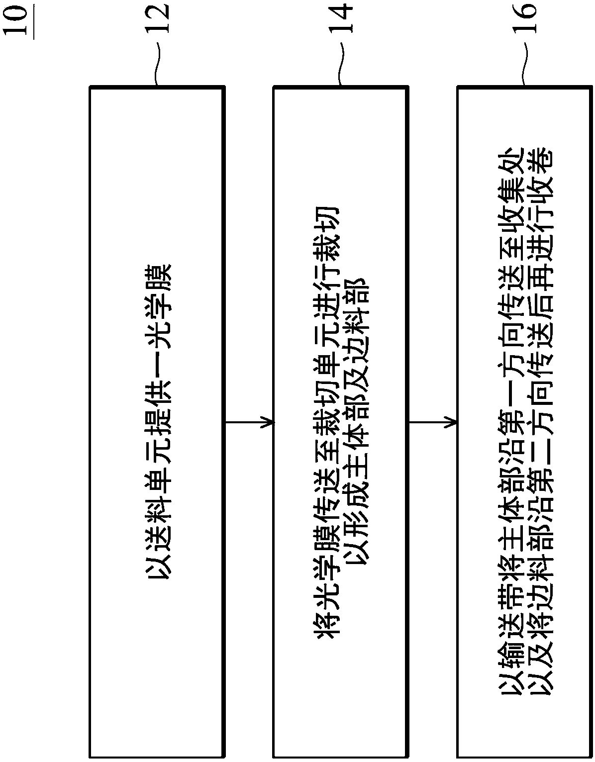
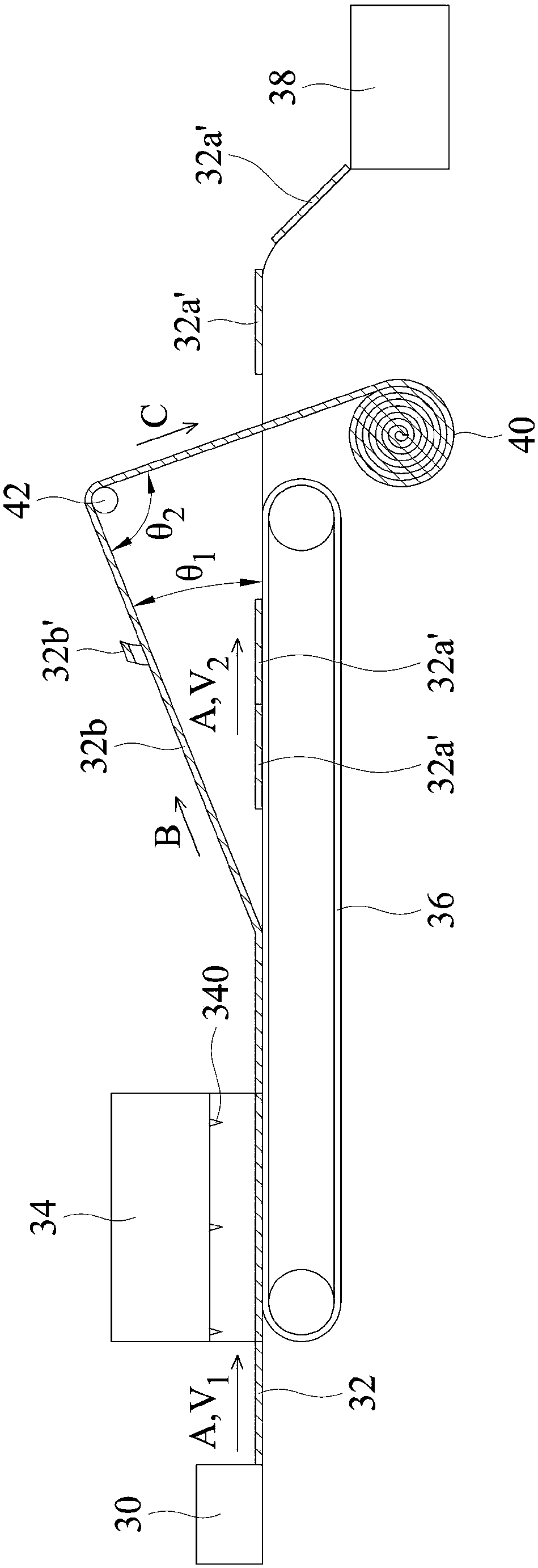
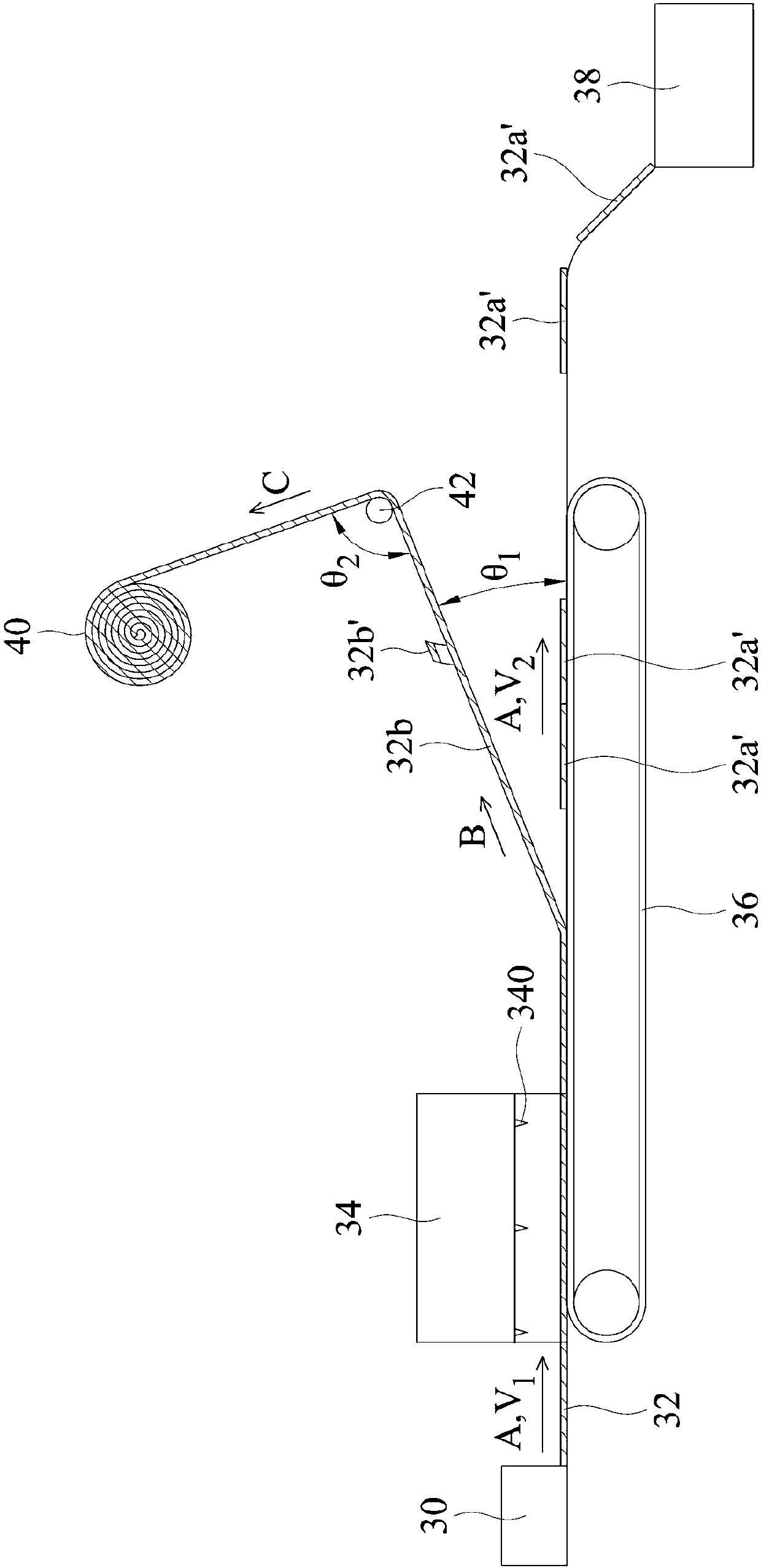
Cutting and winding method for optical film, and cutting knife adopted by method
An optical film and cutting knife technology, which is applied in the field of scrap winding, can solve the problems of interfering with the subsequent manufacturing process of the optical film, damage to the optical film, etc.
- Summary
- Abstract
- Description
- Claims
- Application Information
AI Technical Summary
Problems solved by technology
Method used
Image

Examples
Embodiment Construction
[0052] The cutting and winding method of the optical film of the present disclosure will be described in detail below. It should be understood that the following description provides many different embodiments or examples for implementing different aspects of the present disclosure. The specific components and arrangements described below are only for simple and clear description of the present disclosure. Of course, these are only examples rather than limitations of the present disclosure. Furthermore, repeated reference numerals or designations may be used in different embodiments. These repetitions are only for the purpose of simply and clearly describing the present disclosure, and do not represent any relationship between the different embodiments and / or structures discussed. Furthermore, when it is mentioned that a first element is located on or over a second element, it includes the situation that the first element is in direct contact with the second element. Altern...
PUM
| Property | Measurement | Unit |
|---|---|---|
| width | aaaaa | aaaaa |
Abstract
Description
Claims
Application Information