a help robot

A technology of robot and motor reducer, which is applied in the direction of equipment to help people walk, chairs for patients or special transportation tools, physical therapy, etc. Promote recovery and improve the effect of complications

Active Publication Date: 2020-03-24
HANGZHOU ROBOCT TECH DEV CO LTD
View PDF14 Cites 0 Cited by
  • Summary
  • Abstract
  • Description
  • Claims
  • Application Information

AI Technical Summary

Problems solved by technology

[0004] The purpose of the present invention is to solve the problems that existing wheelchairs and electric wheelchairs require users to sit in the wheelchairs for a long time due to their own characteristics, resulting in the lack of circulation of the user's blood, which may easily cause complications such as pressure sores and osteoporosis. question

Method used


Image

  • a help robot
  • a help robot
  • a help robot

Examples


specific Embodiment approach 1

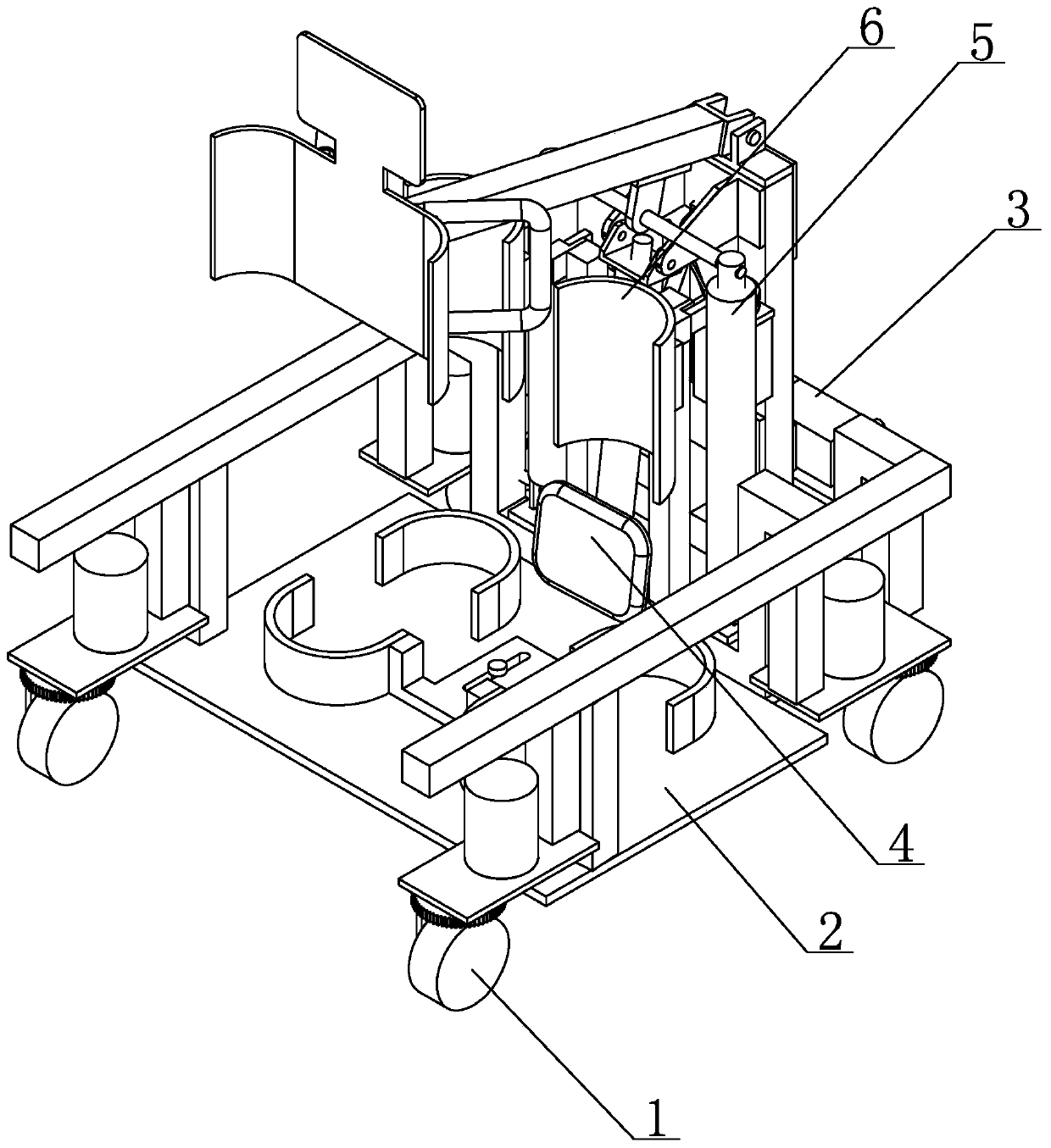
[0021] Specific implementation mode one: combine Figure 1 to Figure 8 Describe this embodiment, a kind of assisting robot of this embodiment, it comprises omnidirectional chassis 1, pedal mechanism 2, control system 3, automatic seat 4, lifting mechanism 5 and knee pad mechanism 6, pedal mechanism 2 installs On the rear portion on the omnidirectional chassis 1, the lifting mechanism 5 is installed on the front portion on the omnidirectional chassis 1, and the knee protection mechanism 6 and the automatic seat 4 are installed on the lifting mechanism 5 successively from top to bottom, and the knee protection mechanism 6 And automatic seat 4 can be adjusted by manually realizing lifting, and control system 3 is installed on the front end of lifting mechanism 5 and controls the action of omnidirectional chassis 1, automatic seat 4, lifting mechanism 5 and knee pad mechanism 6.

specific Embodiment approach 2

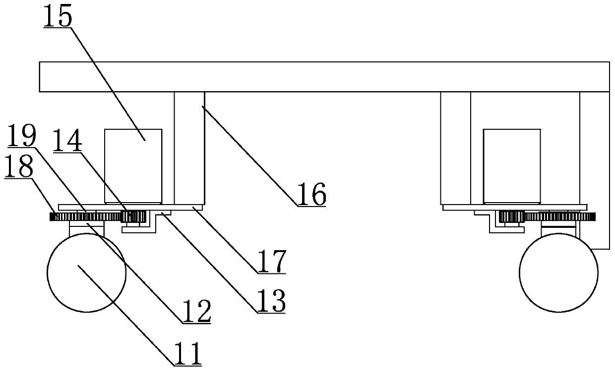
[0022] Specific implementation mode two: combination figure 1 and figure 2 Describe this embodiment, the omni-directional chassis 1 of this embodiment includes a driving mechanism frame 16 and four groups of moving assemblies with the same structure, and the four groups of moving assemblies with the same structure are respectively installed at the four corners of the lower end of the driving mechanism frame 16 . In this way, four moving components are arranged at the lower end of the driving mechanism frame 16. When these four moving components are actually used, by controlling the four moving components respectively, they can move in all directions without dead ends, and can turn on the spot. More flexible, user-friendly and suitable for patients. Other compositions and connections are the same as in the first embodiment.

specific Embodiment approach 3

[0023] Specific implementation mode three: combination figure 1 and figure 2 Describe this embodiment, the moving assembly of this embodiment comprises chassis motor speed reducer 15, driving mechanism mounting plate 17, gear fixing frame 13, chassis pinion 14, chassis large gear 18, chassis rotating shaft 19, driving wheel fixing bracket 12 and drive Wheel 11, driving mechanism mounting plate 17 is installed on the lower end of driving mechanism frame 16, gear holder 13 is installed on the lower end of driving mechanism mounting plate 17, chassis motor reducer 15 is installed on the driving mechanism mounting plate 17, chassis motor reducer 15 The output shaft passes through the drive mechanism mounting plate 17 and is connected with the chassis pinion 14 that is rotatably installed on the gear holder 13. The chassis bull gear 18 is installed on the lower end of the drive mechanism mounting plate 17 by the chassis rotating shaft 19, and the chassis pinion 14 and The chassis...


PUM


Abstract

The invention discloses an assisting robot, and relates to a robot. The problems that due to the characteristics of an existing wheelchair and an existing electric wheelchair, a user needs to sit on the wheelchair for a long term, blood of the user is not circulated, and complications such as pressure sores and osteoporosis are easily caused are solved. A pedal mechanism (2) is installed at the back portion of an omnidirectional chassis (1), a lifting mechanism (5) is installed at the front portion of the omnidirectional chassis (1), and a kneepad plate mechanism (6) and an automatic seat (4)are sequentially installed on the lifting mechanism (5) from top to bottom, and are driven by the lifting mechanism (5) to achieve lifting adjustment; a control system (3) is installed at the front end of the lifting mechanism (5), and controls the omnidirectional chassis (1), the automatic seat (4), the lifting mechanism (5) and the kneepad plate mechanism (6) to move. The assisting robot is usedfor people having the difficulty in moving such as old people, disabled people and paralyzed patients in a hospital and a family.

Description

technical field [0001] The invention relates to a walking aid robot for the elderly, disabled, paralyzed and other handicapped persons in hospitals and families, in particular to an assisting robot, which belongs to the technical field of physiotherapy and rehabilitation nursing. Background technique [0002] At present, most of the elderly, disabled, and paralyzed with limited mobility generally need special personnel to take care of them in their daily life, and cannot take care of themselves in normal daily life. Common walking aids on the market generally include wheelchairs and electric wheelchairs. Although they help travel to a large extent, sitting in a wheelchair for a long time will cause blood circulation, cause complications such as pressure sores and osteoporosis, and have a great impact on health. , And sitting in a wheelchair also has its inconvenience in daily life such as going to the toilet and moving in a small space. [0003] To sum up, due to their own ...

Claims


Application Information

Patent Timeline
Patent Type & Authority Patents(China)
IPC IPC(8): A61G5/06A61H3/04
CPCA61H3/04A61H2201/1207
Inventor 王天王晓奇董石磊孙相宇
Owner HANGZHOU ROBOCT TECH DEV CO LTD
Why Eureka
Try Eureka