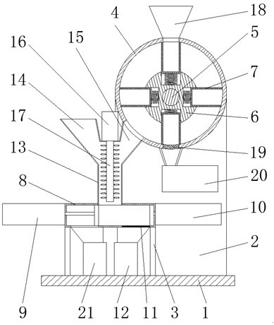
A municipal sludge energy treatment device and its working method

A treatment device and municipal sludge technology, applied in sludge treatment, water/sludge/sewage treatment, dehydration/drying/thickened sludge treatment, etc., can solve the unsuitable small-scale sludge energy treatment and operating costs High efficiency, expensive equipment, etc., to achieve the effect of high sludge removal efficiency, simple and compact structure, and low equipment cost

CN107673578BActive Publication Date: 2020-12-22深圳市广汇源水利建筑工程有限公司
5 Cites 0 Cited by

Patent Information

Authority / Receiving Office
CN · China
Patent Type
Patents(China)
Current Assignee / Owner
Publication Date
2020-12-22

Smart Images

  • Figure 1
    Figure 1
Patent Text Reader

Abstract

The invention discloses an energy regeneration treatment device for municipal sludge and a working method thereof. The energy regeneration treatment device comprises a base, wherein a vertical plate and a bracket are fixed on the top surface of the base respectively; the top of a side face of the vertical plate is connected with a fixed barrel which is transversely arranged; a rotary shaft which is connected onto the vertical plate is arranged in the fixed barrel; the axis of the rotary shaft is located below the axis of the fixed barrel; a roller sleeves the outer part of the rotary shaft; the roller is provided with a plurality of material distribution barrels; the top of the bracket is connected with a squeezing box; a first hydraulic cylinder and a second hydraulic cylinder which are symmetrically arranged are mounted at the outer parts of two sides of the squeezing box respectively; a first piston plate and a second piston plate are connected with output ends, located in the squeezing box, of the first hydraulic cylinder and the second hydraulic cylinder respectively. According to the energy regeneration treatment device for the municipal sludge, disclosed by the invention, squeezing and water removal of sludge and automatic discharging of dewatered sludge blocks are automatically finished; the energy regeneration treatment device is simple and compact in structure, convenient to use, high in sludge dewatering efficiency and low in equipment cost.
Need to check novelty before this filing date? Find Prior Art

Description

technical field

[0001] The invention relates to the technical field of sludge treatment equipment, in particular to a municipal sludge energy treatment device and a working method thereof. Background technique

[0002] With the rapid development of society and economy, the continuous improvement of industrial productivity and human living standards, the generation and discharge of sludge have been increasing. According to conservative statistics, the global annual discharge of municipal sludge alone has exceeded 100 million tons. The disorderly disposal and spread of such a large amount of sludge has aggravated the harm to the environment and has become one of the major problems in the environmental field. In addition to a large amount of organic matter, rich nitrogen, phosphorus, potassium and other nutrients, these sludges also contain harmful components such as heavy metals, pathogenic bacteria, and parasites. Improper disposal can easily lead to secondary pollution of t...

Examples

Embodiment Construction

[0014] The following will clearly and completely describe the technical solutions in the embodiments of the present invention with reference to the accompanying drawings in the embodiments of the present invention. Obviously, the described embodiments are only some, not all, embodiments of the present invention.

[0015] refer to figure 1 , a municipal sludge energy treatment device, including a base 1, a vertical plate 2 and a bracket 3 are respectively fixed on the top surface of the base 1, a horizontally arranged fixed cylinder 4 is connected to the top of the vertical plate 2, and the fixed cylinder 4 There is a rotating shaft 5 connected to the vertical plate 2 inside, the axis of the rotating shaft 5 is located below the axis of the fixed cylinder 4, and the first drive motor (not shown in the figure) is installed on the back of the vertical plate 2, and the output of the first drive motor The end is connected with the shaft end of the rotating shaft 5, and the outer pa...