Full-automatic centrifugal oil purifier

A centrifugal oil purifier technology, applied in liquid separation, separation methods, auxiliary equipment for liquid separation, etc., can solve the problems of inconvenient centralized management for users, inability of users to determine the cause of failure, failure to display, etc., to improve the degree of automation and service life, realize unattended automatic work, and avoid the effect of mechanical seal wear and failure

Pending Publication Date: 2018-07-24
SHILIN LUOHE METALLURGY EQUIP
View PDF8 Cites 3 Cited by
  • Summary
  • Abstract
  • Description
  • Claims
  • Application Information

AI Technical Summary

Problems solved by technology

In addition, the water removed from the oil is collected in the dirt storage box. When the water in the dirt storage box accumulates to a certain extent, it needs to be drained manually. The drain port is mechanically sealed. Frequent use will cause the seal to fail, and the water still remains before draining. It is necessary to stop the oil purifier and repeat the start-up procedure after draining the water. In addition, the centrifugal oil purifier is equipped with automatic protection functions such as air suction, high oil temperature, leakage, and wrong phase sequence. When one of the faults occurs, it will Automatically stop working, the fault cannot be displayed, and the user cannot judge the cause of the fault
[0003] Therefore, the current centrifugal oil purifier needs fixed personnel to guard, occupying labor force, seriously affecting the overall purification efficiency, and human factors have a greater impact on the entire oil purifying process, the operation steps are cumbersome, and it is not convenient for users to realize centralized management

Method used


Image

  • Full-automatic centrifugal oil purifier
  • Full-automatic centrifugal oil purifier

Examples


Embodiment Construction

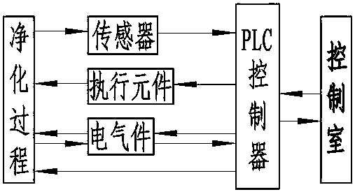
[0019] A fully automatic centrifugal oil purifier, the centrifugal oil purifier is connected with a PLC controller, the PLC controller is provided with a communication port, and the PLC controller is connected with the control room through the communication port to realize remote monitoring and control, which is convenient for users to centralize The body of the PLC controller is equipped with a touch screen and an audible and visual alarm. The touch screen can display the working status, oil outlet pressure and oil temperature in real time. In addition, the centrifugal oil purifier has protection functions such as air suction, high oil temperature, low flow, and leakage. When the above situations occur, the oil purifier will automatically stop, and the sound and light alarm will alarm. The cause of the fault will be displayed on the touch screen in real time, so that users can find out in time Fault, troubleshoot.

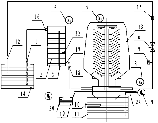
[0020] The centrifugal oil purifier includes a fuel tank 2, ...


PUM


Abstract

The invention relates to a full-automatic centrifugal oil purifier, which consists of an oil tank, a centrifugal cylinder and a pollutant holding box. The oil tank is provided with an oil inlet and anoil outlet, the oil inlet is communicated with an oil inlet pipe, the oil outlet is communicated with the centrifugal cylinder, the centrifugal cylinder is communicated with an oil outlet pipe, boththe oil inlet pipe and the oil outlet pipe are disposed on an oil supply tank, and the pollutant holding box is disposed below the centrifugal cylinder. The full-automatic centrifugal oil purifier also includes a PLC, the oil tank is equipped with a vacuum pump communicated with the oil tank, the oil tank is internally equipped with a liquid level switch I, the centrifugal cylinder is equipped with a self-priming pump I and a main motor, the main motor is connected to the centrifugal cylinder, and the vacuum pump, the liquid level switch I, the self-priming pump I and the main motor are all electrically connected to the PLC. The full-automatic centrifugal oil purifier provided by the invention utilizes the cooperation of one-key startup, automatic water dropping and automatic drainage three parts to realize automatic oil purification, saves labor force, realizes unattended automatic work, avoids low oil purifier purification efficiency caused by keepers' negligence, and improves the automation degree and service life of the oil purifier.

Description

technical field [0001] The invention relates to a fully automatic centrifugal oil purifier. Background technique [0002] The centrifugal oil purifier adopts the principle of centrifugal separation to remove solid impurities, water and air pollutants in the oil. At present, the automation degree of the centrifugal oil purifier is low, and the normal start-up needs to go through various manual operation steps such as oil suction-exhaust-start the motor-open the oil outlet valve-manually adjust the opening size of the oil outlet valve according to the pressure gauge display. When it is used to purify the oil with large water content, it also needs to stop and fall into the water regularly, and then perform the start-up step again, and the work of stopping and falling into the water needs to be repeated. In addition, the water removed from the oil is collected in the dirt storage box. When the water in the dirt storage box accumulates to a certain extent, it needs to be draine...

Claims


Application Information

Patent Timeline
Patent Type & Authority Applications(China)
IPC IPC(8): B01D17/038B01D17/12
CPCB01D17/0217B01D17/12
Inventor 马亚龙崔松浩张进张培成张志培苗伟民李雷于东亮
Owner SHILIN LUOHE METALLURGY EQUIP
Why Eureka
Try Eureka