Check patentability & draft patents in minutes with Patsnap Eureka AI!

A flexible variable-angle array diffractive optical microstructure and its tracked movement method

An optical microstructure and diffractive optics technology, applied in optics, optical components, instruments, etc., can solve the problems of inability to suppress full-band speckle, insufficient speckle suppression effect, large number and types of devices, etc., and achieve stability Speckle suppression effect, small noise interference, small size effect

Active Publication Date: 2019-03-12
ZHEJIANG UNIV OF TECH
View PDF5 Cites 0 Cited by
  • Summary
  • Abstract
  • Description
  • Claims
  • Application Information

AI Technical Summary

Problems solved by technology

[0005] In order to overcome the insufficient effect of speckle suppression in the existing technology, the inability to perform full-band speckle suppression, the number and types of devices used in the system, the complexity of moving parts and impact damage to the instrument, large size, complex structure of the instrument, high energy consumption, The invention provides a flexible variable-angle array diffractive optical microstructure and its crawler-type microstructure with good full-band speckle suppression effect, simple movement mode, easy implementation, system versatility, good robustness, and low cost. The movement method is made of flexible materials, and through the variable-angle array diffraction structure, a crawler-type transmission that can circulate at an infinite constant speed can replace reciprocating mechanical movement to achieve red, green, and blue full-band laser speckle suppression.

Method used


Image

  • A flexible variable-angle array diffractive optical microstructure and its tracked movement method
  • A flexible variable-angle array diffractive optical microstructure and its tracked movement method
  • A flexible variable-angle array diffractive optical microstructure and its tracked movement method

Examples


Embodiment Construction

[0030] The present invention will be further described below in conjunction with the accompanying drawings.

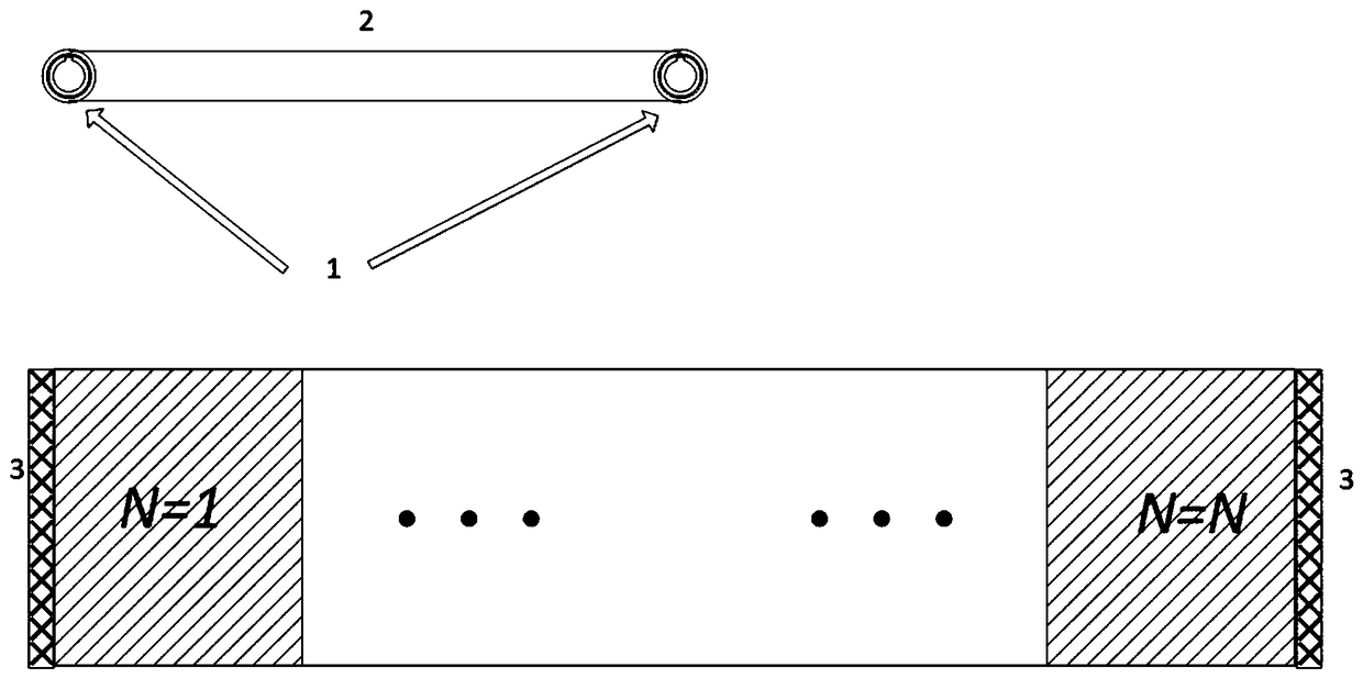
[0031] refer to Figure 1 to Figure 6 , a flexible variable-angle array diffractive optical microstructure, fabricated on PDMS flexible material, is composed of N (N takes 3) groups of one-dimensional binary diffractive optical structures connected end to end. The one-dimensional binary diffractive optical structure is an optical microstructure based on the M sequence (see attached figure 1 And attached figure 2 ), its one-dimensional binary diffractive optical structure pattern is represented by the parameter T, and the parameter T is the minimum unit width of the optical microstructure, and the width of all optical microstructures is represented by an integer multiple of T, and the one-dimensional binary The total width of the diffractive optical structure pattern is T 0 express. The depth of the one-dimensional binary diffractive optical structure is h, and the...


PUM


Abstract

A flexible variable-angle array diffractive optical microstructure is made on a flexible material and is composed of N groups of one-dimensional binary diffractive optical microstructures connected end to end. The flexible variable-angle array diffractive optical microstructure is bent and connected end to end to form a crawler-type structure. The bent flexible variable-angle array diffractive optical microstructure is used as an integral diffractive optical element which includes a front layer and a back layer. Each layer contains N / 2 groups of one-dimensional binary diffractive optical microstructures. The one-dimensional binary diffractive optical microstructures include grating structures and optical microstructures. One-dimensional refers to that each diffractive optical microstructure is a one-dimensional pattern, and binary refers to that the optical path difference formed by the depth of the diffractive optical microstructures is binary. A crawler-type motion method of the flexible variable-angle array diffractive optical microstructure is further provided. The flexible variable-angle array diffractive optical microstructure has the advantages of good full-band speckle suppression effect, simple mode of motion, easy implementation, good system versatility and robustness, and low cost.

Description

technical field [0001] The invention belongs to the field of laser display projection, and in particular relates to a diffractive optical device using a movable diffractive optical device for laser speckle suppression and an adaptive movement method thereof. Background technique [0002] Laser projection display system is getting more and more attention and welcome because of its rich colors, high picture quality, long life, high reliability, high efficiency, low energy consumption and other advantages. However, since laser light is highly coherent light, a picture noise called laser speckle will inevitably be generated. Speckle appears as black spots randomly distributed in the laser spot, and its essence is the random coherent superposition of signals. The existence of speckle seriously affects the quality of images and information. In the field of laser projection display, speckle will degrade the image quality of projection display, cause viewers to experience symptoms ...

Claims


Application Information

Patent Timeline
Patent Type & Authority Patents(China)
IPC IPC(8): G02B27/48G02B26/08
CPCG02B26/0808G02B27/48
Inventor 乐孜纯阿纳托利·拉普查克董文奥历山大·派瑞根
Owner ZHEJIANG UNIV OF TECH
Features
  • R&D
  • Intellectual Property
  • Life Sciences
  • Materials
  • Tech Scout
  • Unparalleled Data Quality
  • Higher Quality Content
  • 60% Fewer Hallucinations
Learn More