Ceramic electronic component and preparation method thereof

A technology of electronic components and ceramics, which is applied in the field of ceramic electronic components and its preparation, can solve problems such as difficulty in identifying ceramic bodies, difficulty in identifying ceramic bodies, and inconsistent performance of ceramic electronic components, so as to avoid structural integrity and prevent insufficient suction Effect

Pending Publication Date: 2018-02-13
GUANGDONG FENGHUA ADVANCED TECH HLDG
View PDF5 Cites 0 Cited by
  • Summary
  • Abstract
  • Description
  • Claims
  • Application Information

AI Technical Summary

Problems solved by technology

[0002] When the ceramic electronic components are designed so that the width and thickness are so close to the extent that it is difficult to distinguish from the appearance, it is difficult to identify each side of the ceramic body when it is analyzed by metallography, so that the required observation surface cannot be accurately obtained, especially Especially for samples with terminal electrodes attached, it is more difficult to identify the sides of the ceramic body because the two end faces of the exposed internal electrodes are covered by the terminal electrodes
[0003] Furthermore, when such ceramic electronic components are taped and packaged, because the sides of the ceramic body cannot be identified, the ceramic electronic components are taped with different orientations. As a result, when customers use it, some ceramic electronic components are The electrodes are mounted on the circuit board in a manner parallel to the circuit board, and some ceramic electronic components are mounted on the circuit board in such a way that the inner electrodes are perpendicular to the circuit board, resulting in inconsistent performance of the ceramic electronic components

Method used


Image

  • Ceramic electronic component and preparation method thereof
  • Ceramic electronic component and preparation method thereof
  • Ceramic electronic component and preparation method thereof

Examples


Embodiment 1

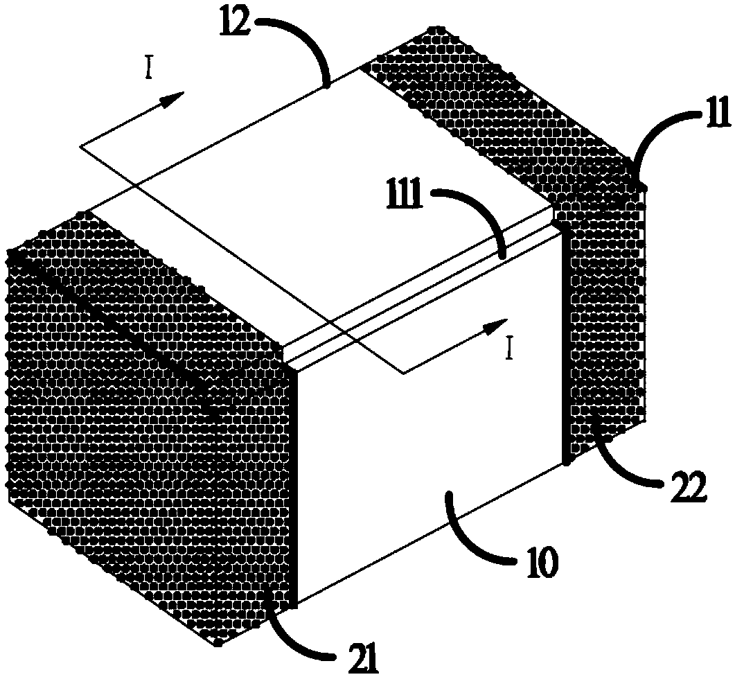
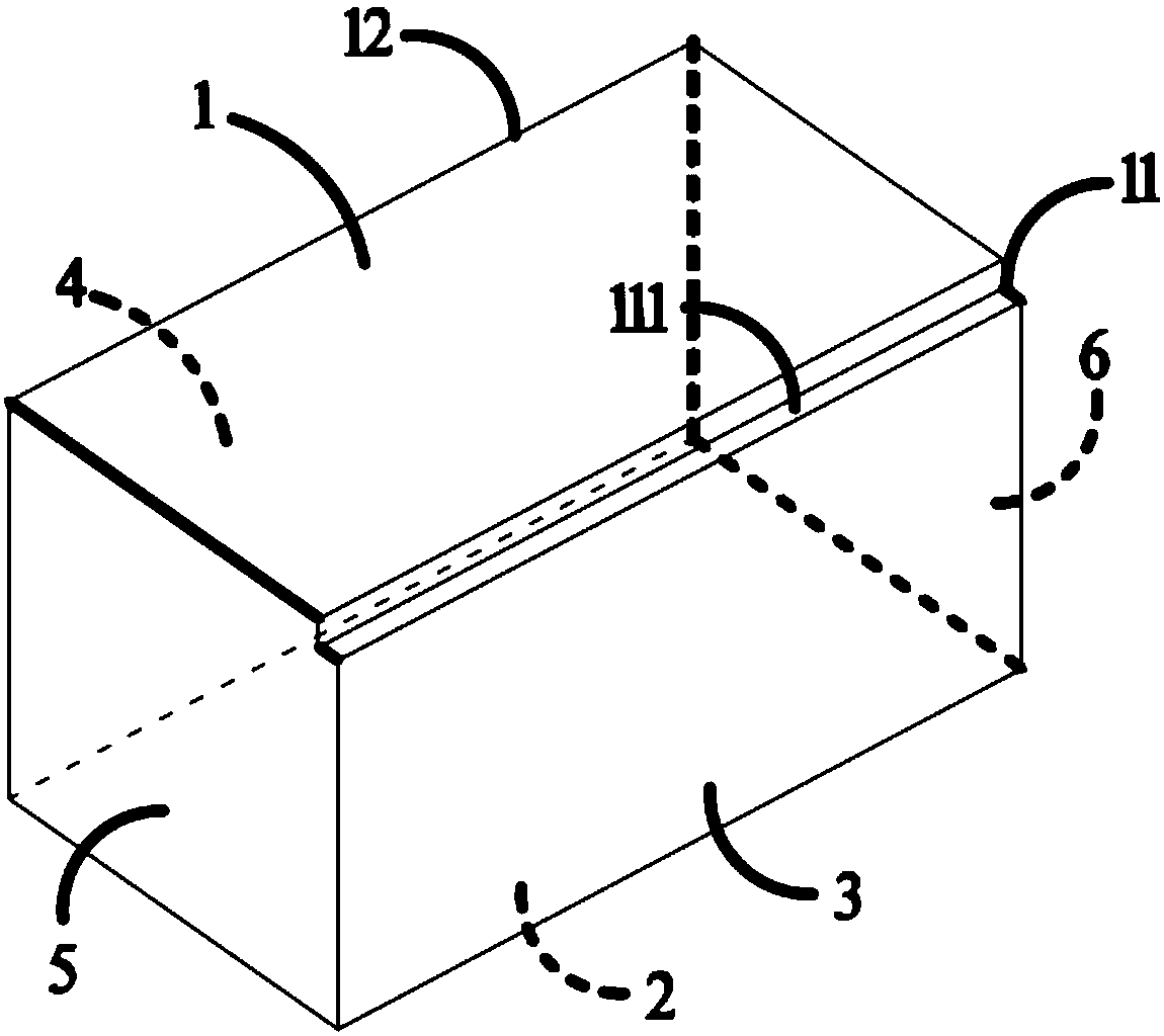
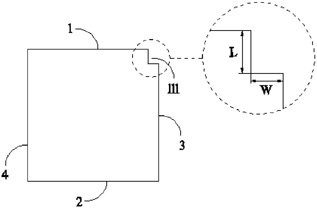
[0034] Such as figure 1 , figure 2 and image 3 As shown, a ceramic electronic component according to an embodiment of the present invention includes a ceramic body 10, the ceramic body 10 is a rectangular body, and includes a first side 1 and a second side 2 opposite to each other, and a third side opposite to each other. 3 and the fourth side 4 and the first end face 5 and the second end face 6 opposite to each other; the first side 1 and the second side 2 are perpendicular to the thickness direction of the ceramic body 10, and the third side 3 and the fourth side 4 are perpendicular to the thickness direction of the ceramic body 10. The width direction of the ceramic body 10 is perpendicular, the first end face 5 and the second end face 6 are perpendicular to the length direction of the ceramic body 10; the edge at the intersection of the first side 1 and the third side 3 is the first edge 11, the second The edge at the intersection of one side 1 and the fourth side 4 is...

Embodiment 2

[0071] A ceramic electronic component in this embodiment of the present invention differs from the ceramic electronic component in Embodiment 1 only in that in this embodiment, the length of the first groove 111 is shorter than the length of the first edge 11 .

[0072] The position of the first groove 111 on the first edge 11 is not particularly limited, but in order to facilitate identification of each side of the ceramic electronic component, the first groove 111 is not completely covered by the first terminal electrode 21 and the second terminal electrode 22 .

Embodiment 3

[0074] Such as Figure 4 As shown, a ceramic electronic component in the embodiment of the present invention differs from the ceramic electronic component in Embodiment 1 in that: in this embodiment, the second edge 12 is provided with a second groove 112; The depth of the section of the groove 111 on the first side 1 is L 1 , the depth of the section of the first groove 111 on the third side 3 is W 1 , the depth of the section of the second groove 112 on the first side 1 is L 2 , the depth of the section of the second groove 112 on the fourth side 4 is W 2 ; L 1 , W 1 , L 2 and W 2 all the same or different.

[0075] It should be noted that, in this embodiment, the first groove 111 and the second groove 112 are both arranged on the two lengthwise edges of the first side surface, in fact, the first groove and the second groove It can also be arranged on the edges in the two length directions of the third side.

[0076] Further, the vertical section of the second groov...


PUM

PropertyMeasurementUnit
Thicknessaaaaaaaaaa

Abstract

The invention relates to a ceramic electronic component and a preparation method thereof, and belongs to the field of an electronic element. The ceramic electronic component comprises a ceramic body,wherein the ceramic body is a rectangular body and comprises a first side surface, a second side surface, a third side surface, a fourth side surface, a first end surface and a second end surface; thefirst side surface and the second side surface are in opposite arrangement and are vertical to the thickness direction of the ceramic body; the third side surface and the fourth side surface are in opposite arrangement and are vertical to the width direction of the ceramic body; the first end surface and the second end surface are in in opposite arrangement and are vertical to the length direction of the ceramic body; a groove is formed in the edge in the any one length direction of the ceramic body; the depths of the cross section of the groove in the two located side surfaces are different;or grooves are formed in the edges in the two length directions of the first side surface or the third side surface. The ceramic electronic component provided by the invention has the advantage thatthrough the formation of the grooves in the edge of the ceramic body, each side surface can be easily recognized.

Description

technical field [0001] The invention relates to a ceramic electronic component and a preparation method thereof, belonging to the field of electronic components. Background technique [0002] When the ceramic electronic components are designed so that the width and thickness are so close to the extent that it is difficult to distinguish from the appearance, it is difficult to identify the various sides of the ceramic body when it is analyzed by metallography, so that the required observation surface cannot be accurately obtained, especially Especially for samples with terminal electrodes attached, it is more difficult to identify the sides of the ceramic body because the two end faces where the internal electrodes are exposed are covered by the terminal electrodes. [0003] Furthermore, when such ceramic electronic components are taped and packaged, because the sides of the ceramic body cannot be identified, the ceramic electronic components are taped with different orientat...

Claims


Application Information

Patent Timeline
IPC IPC(8): H05K5/02H05K7/02
CPCH05K5/02H05K5/0252H05K7/02
Inventor 陆亨卓金丽廖庆文安可荣唐浩宋子峰
Owner GUANGDONG FENGHUA ADVANCED TECH HLDG
Why Eureka
Try Eureka