
Energy saving device for buildings or channels

An energy-saving device and channel technology, applied in the direction of electrical components, electric switches, circuits, etc., can solve the problems of easy to close the switch by mistake, shorten the service life, and not close tightly, so as to prevent electric shock accidents, ensure power waste, The effect of easy operation

Inactive Publication Date: 2018-02-16
JIANGSU SUZHONG CONSTR GROUP
View PDF4 Cites 0 Cited by
  • Summary
  • Abstract
  • Description
  • Claims
  • Application Information

AI Technical Summary

Problems solved by technology

[0002] In underground buildings or underground passages, such as basements, tunnels, sewers and other dark places, lighting or some tools are essential for daily maintenance or inspection. The traditional switch uses a push-type control switch. Or a knife-type switch, but both of these switches have the disadvantages of loose closing, easy to get dust, and easy to close the switch by mistake, and this usually takes a long time until the next daily maintenance or repair. Only inspections can be found, which will inevitably cause a lot of waste of power, and will also use electrical devices to overload and shorten the service life

Method used


Image

  • Energy saving device for buildings or channels
  • Energy saving device for buildings or channels
  • Energy saving device for buildings or channels

Examples


Embodiment Construction

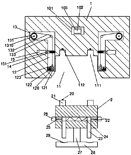
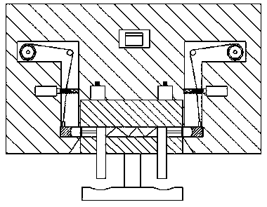
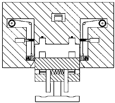
[0019] Such as Figure 1-Figure 5 As shown, an energy-saving device for building passages of the present invention includes a control gate seat 1 and a control gate head 2. A control insertion chamber 11 is opened in the lower part of the control gate seat 1, and the upper part of the control insertion chamber 11 is communicated with a The insertion guide port 111, the upper part of the insertion guide port 111 is fixed with a power connection piece 112, and the left and right sides of the control gate 1 are provided with a symmetrical power connection mechanism, and the power connection mechanism includes a lower chamber 12 extending in the up and down direction and the upper chamber 13 extending in the left and right directions, the lower chamber 12 communicates with the upper chamber 13, the lower part of the lower chamber 12 is provided with a cross-connecting groove 120, and the mouth of the cross-connecting groove 120 faces the The control insertion cavity 11 and the cro...


PUM


Abstract

The invention discloses an energy saving device for buildings or channels, which includes a control gate base and a control gate head. A control insertion cavity is arranged inside the control gate base. Insertion guide ports are arranged in the top of the control insertion cavity in a communicating manner. An electricity connecting piece is fixedly arranged on the top of each insertion guide port. Electricity connecting mechanisms symmetrically installed are respectively arranged on the left and right sides of the control gate base. Each electricity connecting mechanism includes a lower chamber extending in the up-down direction and an upper chamber extending in the left-right direction. Each lower chamber and the corresponding upper chamber are communicated with each other. A transverseconnecting slot is arranged at the bottom of each lower chamber. The transverse connecting slots face towards the control insertion cavity, and are communicated with the control insertion cavity. A shift pressure spring is fixedly arranged in the outer side of each transverse connecting slot. The energy saving device has a simple structure, is easy to operate, adopts simple transmission inside, and costs low. The energy saving device prevents the interference of outside ashes and water drops to the electric energy control gate, reduces the waste of energy caused by the failure to discover a switch opened by mistaken touch, and ensures the electrical safety.

Description

technical field [0001] The invention relates to the technical field of energy saving, in particular to an energy saving device for building passages. Background technique [0002] In underground buildings or underground passages, such as basements, tunnels, sewers and other dark places, lighting or some tools are essential for daily maintenance or inspection. The traditional switch uses a push-type control switch. Or a knife-type switch, but both of these switches have the disadvantages of loose closing, easy to get dust, and easy to close the switch by mistake, and this usually takes a long time until the next daily maintenance or repair. Only inspections can be found, which will inevitably cause a lot of waste of power, and will also use electrical devices to overload and shorten the service life. In view of this situation, there is a need for an efficient, safe and guaranteed device that will not be affected by dust or water droplets, and will not cause waste due to acci...

Claims


Application Information

Patent Timeline
Patent Type & Authority Applications(China)
IPC IPC(8): H01H9/20
CPCH01H9/20
Inventor 于兵王跃周德龙
Owner JIANGSU SUZHONG CONSTR GROUP
Features
  • Generate Ideas
  • Intellectual Property
  • Life Sciences
  • Materials
  • Tech Scout
  • Unparalleled Data Quality
  • Higher Quality Content
  • 60% Fewer Hallucinations
Learn More