Eureka AIR delivers breakthrough ideas for toughest innovation challenges, trusted by R&D personnel around the world.

Full screen, terminal equipment and manufacturing method of terminal equipment

A terminal equipment, full-screen technology, applied in branch equipment, TV, color TV, etc., can solve problems such as poor user experience, troublesome operation, uneven dispensing process, etc., to solve the problem of camera being interfered by light, occupation Small space, avoiding the effect of complex dispensing process

Inactive Publication Date: 2018-02-16
NUBIA TECHNOLOGY CO LTD
View PDF8 Cites 52 Cited by
  • Summary
  • Abstract
  • Description
  • Claims
  • Application Information

AI Technical Summary

Problems solved by technology

[0005] The main purpose of the present invention is to propose a full screen, a terminal device and a manufacturing method thereof, aiming at solving the problem of light interference of the camera taking pictures of the full screen in the prior art, uneven dispensing process and troublesome operation, thus bringing inconvenience to the user. The technical problems of using the sense of experience

Method used


Image

  • Full screen, terminal equipment and manufacturing method of terminal equipment
  • Full screen, terminal equipment and manufacturing method of terminal equipment
  • Full screen, terminal equipment and manufacturing method of terminal equipment

Examples


Embodiment 1

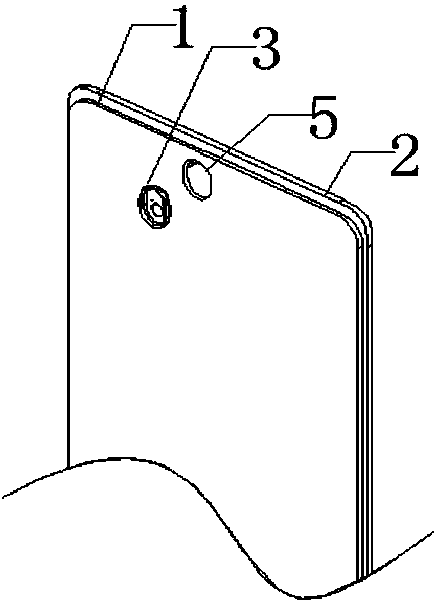
[0066] Such as image 3 As shown, the schematic exploded view of the structure of the first embodiment proposed by the full screen of the present invention, the full screen includes the LCM component 1, the TP cover plate 2 and the light-shielding member 3, the TP cover plate 2 is pasted on the LCM component 1, and the The LCM module 1 is provided with a mounting groove 5 for embedding the camera 4, and a light shielding member 3 covering the lens of the camera 4 is provided in the mounting groove 5, and is used to block the light emitted by the full screen from entering the shooting of the camera 4. area (such as Figure 9 As shown), the position of the shading member 3 corresponding to the lens of the camera 4 is provided with a through hole 6, so that the camera 4 can take pictures through the through hole 6.

[0067] Specifically, in order to better avoid the interference of the light emitted by the full screen and affect the work of the camera 4, the light-shielding memb...

Embodiment 2

[0075] Figure 4 A schematic structural diagram of the second embodiment proposed for the full screen of the present invention; Figure 5 for Figure 4 The Y-Y cross-sectional view; such as Figure 4 and Figure 5 As shown, the present invention proposes a second embodiment of the full screen. The technical solution of the second embodiment is basically similar to that of the first embodiment, the difference is that the installation groove 5 of the second embodiment is U-shaped; and the shading member 3 is an open cylindrical structure, and the through hole 6 is arranged 3 in the middle of the cylinder bottom, the cylinder cross section of the shading member 3 is U-shaped. In this way, the structure of the shading member 3 can be further simplified under the premise of ensuring that the light emitted by the full screen does not interfere with the work of the camera 4 , which not only reduces equipment costs, but also takes up less space.

[0076] The full screen of Embodi...

Embodiment 3

[0085] Figure 6 A schematic structural diagram of the third embodiment provided for the terminal device of the present invention; Figure 7 for Figure 6 The schematic diagram of the structural decomposition, such as Figure 6 and Figure 7 As shown, the present invention also proposes a terminal device, which includes a body, a camera 4 component and a full screen. The body and the camera 4 component are existing technologies in the field, and will not be described in detail in the present invention. The camera 4 components include Figure 6 and Figure 7 The front camera 4 and the rear camera 4 (not shown in the figure).

[0086] Specifically, the terminal device may be other intelligent terminal devices such as a mobile terminal and a palmtop computer, which are not listed here.

[0087] The full screen of the terminal device in the third embodiment includes an LCM component 1, a TP cover 2 and a light-shielding member 3, the TP cover 2 is attached to the LCM compone...


PUM


Abstract

The invention discloses a full screen, terminal equipment and a manufacturing method of the terminal equipment. The full screen comprises an LCM (LCD Module) assembly, a TP cover plate and a light shading part, wherein the TP cover plate is attached to the LCM assembly; the LCM assembly is provided with a mounting groove for embedding a camera; the light shading part covering the camera is arranged in the mounting groove, and used for covering a shooting area in which light emitted by the full screen enters the camera; and a through hole is formed in a position which corresponds to a lens of the camera on the light shading part, so that the camera can be used for shooting through the through hole. According to the full screen, the terminal equipment and the manufacturing method of the terminal equipment disclosed by the invention, a display screen can be isolated through the light shading part, thereby completely solving the problem that the camera is interfered by light. Moreover, a small space is occupied, and the screen-to-body ratio of the full screen is realized better. In addition, the problem concerned with falling reliability testing or fuzzy stress on the camera caused byinterference due to dispensing in the prior art are solved, and the technical problem of complicated dispensing process is solved. Moreover, the full screen has the beneficial effect of simple assembling process and low cost.

Description

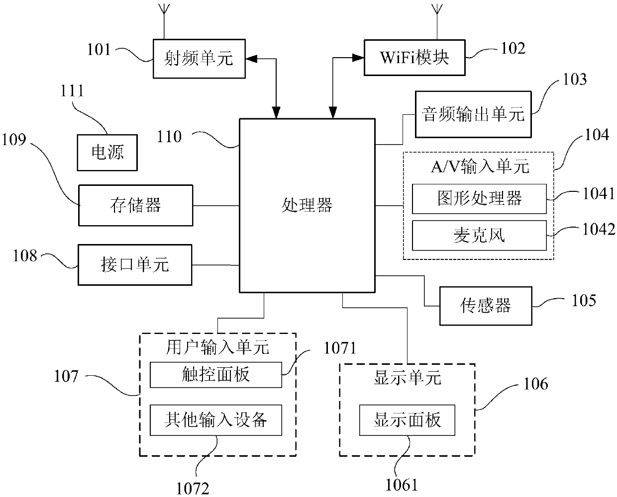
technical field [0001] The invention relates to the technical field of terminal equipment control, in particular to a full screen, a terminal equipment and a manufacturing method thereof. Background technique [0002] With the development of terminal equipment, full screens are gradually appearing on terminal equipment, such as smart phones. The full-screen mobile phone is visually more beautiful, and the second is to reduce the area of ​​the mobile phone, so that a larger screen can be inserted under the same size mold. Simply put, a full-screen mobile phone can bring a better visual experience, and at the same time, the appearance will also look more beautiful. [0003] However, the full-screen mobile phone also has some shortcomings: because the full-screen mobile phone increases the screen ratio as much as possible, there will also be some technical problems, such as the built-in full-screen front camera will be affected by the light of the full-screen, Because the lig...

Claims


Application Information

Patent Timeline
IPC IPC(8): H04M1/02H04N5/225G03B11/00G03B11/04G03B30/00
CPCH04M1/0264H04M1/0266G03B11/00G03B11/04H04N23/50
Inventor 杨秀文
Owner NUBIA TECHNOLOGY CO LTD
Why Eureka
Eureka Blog
Learn More