Electromagnetic heating cooker, control method and control device thereof

A control method and technology of a control device, which are applied to electric heating devices, induction heating control, induction heating devices, etc., can solve the problems of resonant circuit 3 vibration stop, heating, and comparator E output inversion.

Active Publication Date: 2020-11-03
ZHEJIANG SHAOXING SUPOR DOMESTIC ELECTRICAL APPLIANCE CO LTD
View PDF2 Cites 0 Cited by
  • Summary
  • Abstract
  • Description
  • Claims
  • Application Information

AI Technical Summary

Problems solved by technology

[0005] However, when the mains ACV crosses zero in this existing electromagnetic cooker, the voltages collected by points N and P in the synchronous circuit 5 cannot cause the output of the comparator E in the PWM modulation circuit 61 to reverse, so that the IGBT4 cannot be turned on again. , causing the resonant circuit 3 to stop vibrating and heating to stop

Method used


Image

  • Electromagnetic heating cooker, control method and control device thereof
  • Electromagnetic heating cooker, control method and control device thereof
  • Electromagnetic heating cooker, control method and control device thereof

Examples


Embodiment 1

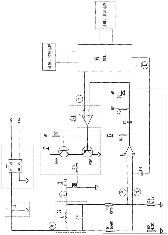
[0046] The induction cooker of this embodiment includes: a resonant circuit and an IGBT. The IGBT forms an electromagnetic oscillation circuit together with the resonant circuit and an external power supply (mains power), so that a high-frequency magnetic field change is generated by the mutual cooperation of the coil disk and the capacitor in the resonant circuit. , and then a magnetic field vortex is formed between the induction cooker and the pot, causing the vibration of metal atoms in the pot, causing the pot to heat up, thereby achieving the purpose of heating the food.

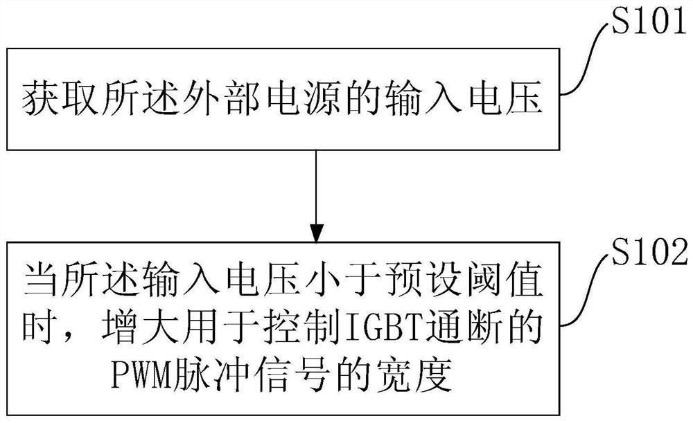
[0047] figure 2 This is a schematic flowchart of the control method provided in this embodiment. like figure 2 As shown, the control method of this embodiment includes:

[0048] S101. Obtain the input voltage of the external power supply.

[0049] In the actual environment, obtaining the input voltage of the external power supply can be achieved by various methods. for example:

[0050] In some o...

Embodiment 2

[0074] The induction cooker of this embodiment includes: a resonant circuit and an IGBT. The IGBT forms an electromagnetic oscillation circuit together with the resonant circuit and an external power supply (mains power), so that a high-frequency magnetic field change is generated by the mutual cooperation of the coil disk and the capacitor in the resonant circuit. , and then a magnetic field vortex is formed between the induction cooker and the pot, causing the vibration of metal atoms in the pot, causing the pot to heat up, thereby achieving the purpose of heating the food.

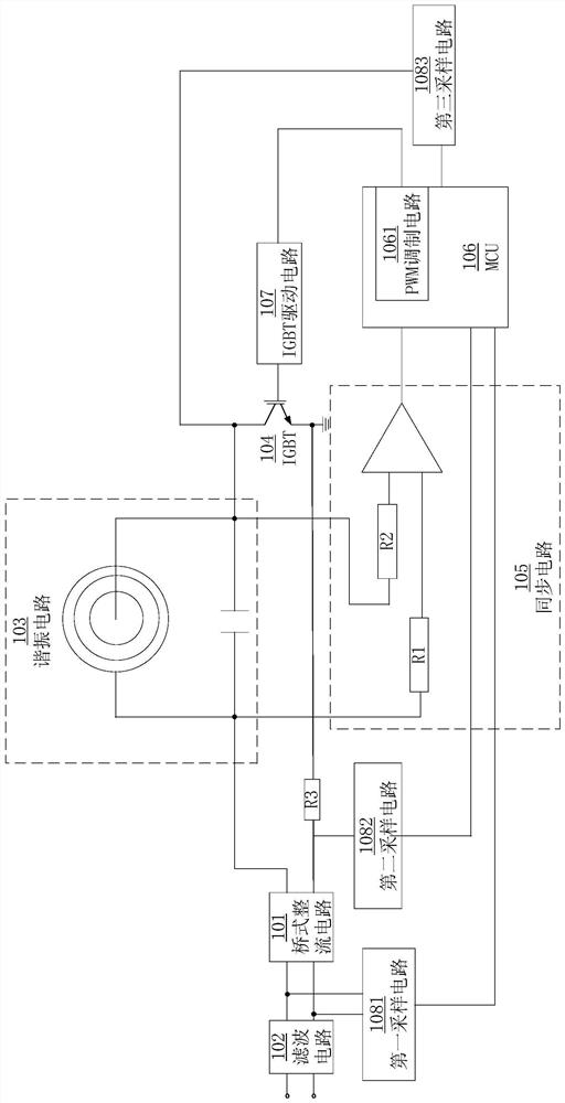
[0075] Figure 4 It is a schematic structural diagram of the control device 200 provided in this embodiment. like Figure 4 As shown, the control apparatus 200 of this embodiment can execute the control method of Embodiment 1, which includes: a first sampling module 202 and a processing module 201 electrically connected to the first sampling module 202 . Wherein, the first processing module 201 is use...

Embodiment 3

[0089] The induction cooker of this embodiment includes: a resonant circuit and an IGBT. The IGBT forms an electromagnetic oscillation circuit together with the resonant circuit and an external power supply (mains power), so that a high-frequency magnetic field change is generated by the mutual cooperation of the coil disk and the capacitor in the resonant circuit. , and then a magnetic field vortex is formed between the induction cooker and the pot, causing the vibration of metal atoms in the pot, causing the pot to heat up, thereby achieving the purpose of heating the food.

[0090] Figure 5 It is a schematic structural diagram of the control device 300 provided in this embodiment. like Figure 5 As shown, the control device 300 in this embodiment includes: a memory 302 storing an executable instruction set, and a processor 301 . The processor 301 is configured to invoke the executable instruction set in the memory 302 to execute the control method in the first embodiment...


PUM


Abstract

The present invention provides an electromagnetic heating cooker and its control method and control device. The electromagnetic heating cooker includes: a resonant circuit and an IGBT, and the resonant circuit, IGBT and an external power supply form an electromagnetic oscillation circuit; the control method includes: obtaining the The input voltage of the external power supply; when the input voltage is less than the preset threshold, increase the width of the PWM pulse signal used to control the IGBT on and off. The electromagnetic heating cooker and its control method and control device of the present invention can prevent the resonant circuit of the electromagnetic heating cooker from vibrating without adding a timing circuit or a coupling circuit, and are easy to use and low in cost.

Description

technical field [0001] The invention relates to an electromagnetic heating cooker, a control method and a control device thereof, and belongs to the technical field of kitchen appliances. Background technique [0002] Heating food by electromagnetic induction is not only clean and hygienic, but also convenient and efficient, so it is used in more and more kitchen appliances, such as induction cookers, rice cookers and hot pots. [0003] figure 1 It is a schematic circuit diagram of an induction cooker in the prior art. like figure 1 As shown, the induction cooker includes a bridge rectifier circuit 1 , a filter circuit 2 , a resonance circuit 3 , an IGBT 4 , a synchronization circuit 5 , an MCU 6 , a PWM modulation circuit 61 , and an IGBT drive circuit 7 , which are connected in sequence. After the AC mains ACV passes through the bridge rectifier circuit 1 and the filter circuit 2, the DC voltage is obtained at point A. [0004] In the initial stage, the D and R points ...

Claims


Application Information

Patent Timeline
Patent Type & Authority Patents(China)
IPC IPC(8): H05B6/06H05B6/12
CPCH05B6/062H05B6/1209
Inventor 周宇杨剑赵礼荣
Owner ZHEJIANG SHAOXING SUPOR DOMESTIC ELECTRICAL APPLIANCE CO LTD
Why Eureka
Try Eureka