Electronic ballast

An electronic ballast and resistance technology, applied in electric light sources, electrical components, lighting devices, etc., can solve problems such as difficulty in controlling the working current or power of light-emitting elements, and difficulty in controlling the output voltage and output current of self-excited electronic ballasts. To achieve the effect of controlling the operating frequency

Inactive Publication Date: 2013-07-24
DELTA ELECTRONICS (SHANGHAI) CO LTD
View PDF4 Cites 1 Cited by
  • Summary
  • Abstract
  • Description
  • Claims
  • Application Information

AI Technical Summary

Problems solved by technology

In the self-excited circuit, due to the limitation of its own circuit structure, the operating frequency of the self-excited resonant circuit is determined by the load, so it is difficult to control the output voltage and output current of the self-excited electronic ballast, and it is difficult to control the operating current of the light-emitting element or power

Method used


Image

  • Electronic ballast
  • Electronic ballast
  • Electronic ballast

Examples


Embodiment 2

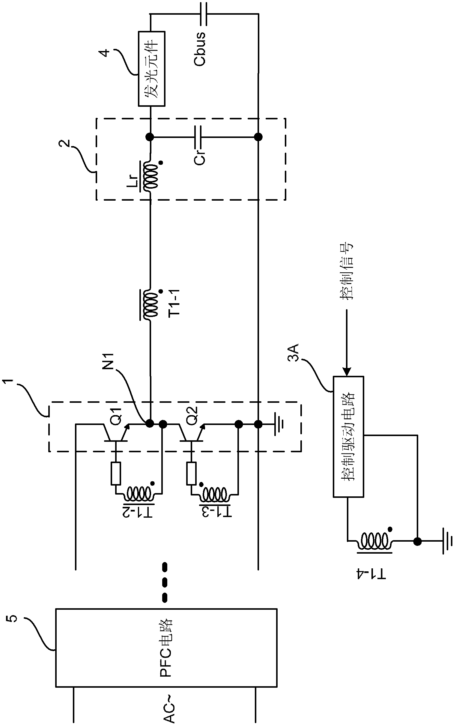
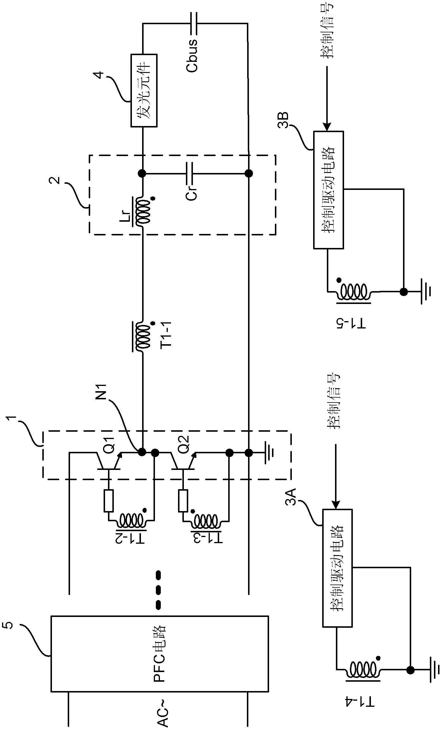
[0038] In the second embodiment, by setting the induction windings T1-4 and T1-5, the on-times of the transistors Q1 and Q2 are both shortened, so that the adjustment range of the operating frequency of the electronic ballast can be higher than that of the first embodiment. Embodiment 2 can be adopted when the operating frequency range of the electronic ballast is required to be variable. Compared with the first embodiment, the second embodiment can realize more in-depth control of the electronic ballast, and can achieve a large degree of control over the operating current of the light-emitting element.

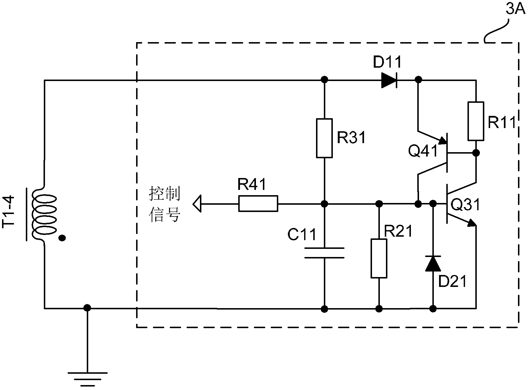
[0039] In an embodiment of the present invention, the control drive circuit 3A or 3B may be a circuit capable of controlling the voltage across the induction winding. For example, it can be a clamping circuit, which can receive a control signal and pull down the voltage across the induction winding during operation so that the control winding coupled with the induction windin...


PUM


Abstract

The invention discloses an electronic ballast. The electronic ballast comprises a square-wave generator, a transformer, a resonant circuit, and at least one control driving circuit, wherein the square-wave generator comprises a plurality of switch elements, the switch elements achieve breakover alternately and are used for converting direct current input voltage into square-wave alternating voltage and outputting the square-wave alternating voltage, the transformer comprises a drive winding, a plurality of control windings, and as least one induction winding, the drive winding, the control windings and the at lease one induction winding are mutually coupled, the plurality of the control windings are electrically connected with control ends of the plurality of switch elements respectively to control the plurality of switch elements to achieve breakover alternately, the resonant circuit and the drive winding form a resonant loop, the resonant circuit is electrically connected with an output end of the square-wave generator to drive a luminous element, and the at least one control drive circuit is connected with two ends of the induction winding in parallel and is used for receiving a control signal to control voltages of the two ends of the induction winding to control breakover time of at least one switch element. The invention provides the electronic ballast which is controllable in working frequency to stabilize working current or working power of the luminous element.

Description

technical field [0001] The invention relates to ballast technology, in particular to an electronic ballast capable of controlling the working current and power of light-emitting elements. Background technique [0002] At present, compared with electromagnetic ballasts, electronic ballasts have the advantages of high efficiency, light weight, no flicker, and no audible noise, so they are widely used. Among various electronic ballasts that drive light-emitting elements (such as fluorescent lamps), self-excited electronic ballasts are relatively simple and cost-effective electronic ballasts. [0003] However, the self-excited electronic ballast has the following problems. In the self-excited circuit, due to the limitation of its own circuit structure, the operating frequency of the self-excited resonant circuit is determined by the load, so it is difficult to control the output voltage and output current of the self-excited electronic ballast, and it is difficult to control th...

Claims


Application Information

Patent Timeline
Patent Type & Authority Applications(China)
IPC IPC(8): H05B41/282H05B41/36
CPCH05B41/3927H05B41/282H05B41/36H05B41/2828
Inventor 钟燕张伟强应建平
Owner DELTA ELECTRONICS (SHANGHAI) CO LTD
Why Eureka
Try Eureka