
Cooperative action control method, device and system of moving parts

A technology of moving parts and coordinated actions, which is applied in the direction of fluid pressure actuators, servo motor components, servo motors, etc., and can solve the problem of poor control accuracy of the action coordination of multiple moving parts and inaccurate control of the response time of multiple driving cylinders , Low accuracy of motion trajectory control of multiple moving parts, etc., to achieve the effect of improving accuracy, reducing time error, and improving accuracy

Active Publication Date: 2015-11-11
HUNAN ZOOMLION INTELLIGENT TECH +1
View PDF9 Cites 0 Cited by
  • Summary
  • Abstract
  • Description
  • Claims
  • Application Information

AI Technical Summary

Problems solved by technology

[0007] The invention provides a method, device and system for controlling the coordinated action of moving parts, which are used to solve the inaccurate control of the response time of multiple driving cylinders and the cooperative control of the actions of multiple moving parts in the prior art when multiple moving parts move cooperatively Poor accuracy, resulting in low accuracy of motion trajectory control of multiple moving parts

Method used


Image

  • Cooperative action control method, device and system of moving parts
  • Cooperative action control method, device and system of moving parts
  • Cooperative action control method, device and system of moving parts

Examples


Embodiment 1

[0083] Embodiment 1 of the present invention provides a method for controlling coordinated actions of moving parts, the flow of which is as follows Figure 6 shown, including the following steps:

[0084] Step S101: Applying a preparatory current smaller than an activation current threshold to each electric proportional control valve of the multi-way valve, so that each electric proportional control valve of the multi-way valve is in a ready state.

[0085] The multi-way valve that controls the action of the driving cylinder is controlled by a current signal, and each electric proportional control valve has a current dead zone. During the control process of the multi-way valve, due to the influence of various factors, the The spools have different responses. In order to make the spools of the electric proportional control valves respond simultaneously, the present invention adopts a "preparation" current mode. In order to make multiple moving parts cooperate, after the cooper...

Embodiment 2

[0099] The method for controlling the coordinated action of moving parts provided by Embodiment 2 of the present invention further increases the control of the action time of each electric proportional control valve on the basis of the method of Embodiment 1, thereby further improving the coordination and consistency of the actions of multiple moving parts. Process such as Figure 7 shown, including the following steps:

[0100] Step S201: Applying a preparatory current smaller than an activation current threshold to each electric proportional control valve of the multi-way valve, so that each electric proportional control valve of the multi-way valve is in a ready state.

[0101] Refer to step S101, which will not be repeated here.

[0102] Step S202: Determine the action time of the control current on each electric proportional control valve according to the response delay time of each driving oil cylinder relative to the corresponding electric proportional control valve. ...


PUM


Abstract

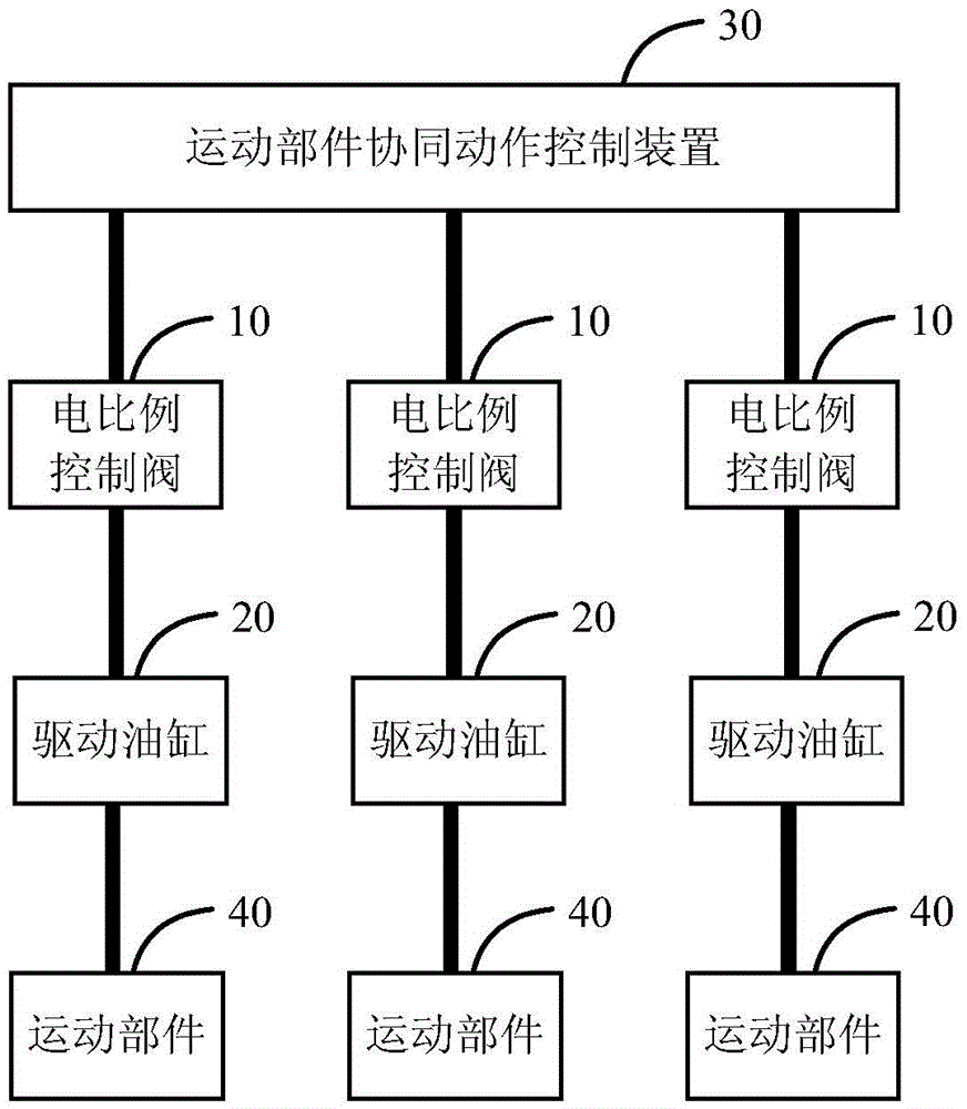
The invention discloses a movement component coordination action control method, device and system. The movement component coordination action control method comprises the steps that a preparation current lower than an activate current threshold acts on each electric proportional control valve of a multi-way valve so that each electric proportional control valve of the multi-way valve can be in a preparation state; in the preparation state, a control current not lower than the activate current threshold acts on each electric proportional control valve of the multi-way valve so that each electric proportional control valve can respond; the electric proportional control valves control corresponding driving oil cylinders to act, and then movement components driven by the driving oil cylinders are controlled to act. The invention further discloses the device and system for realizing the movement component coordination action control method.

Description

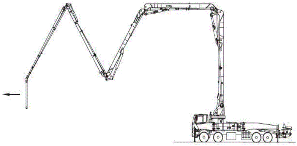
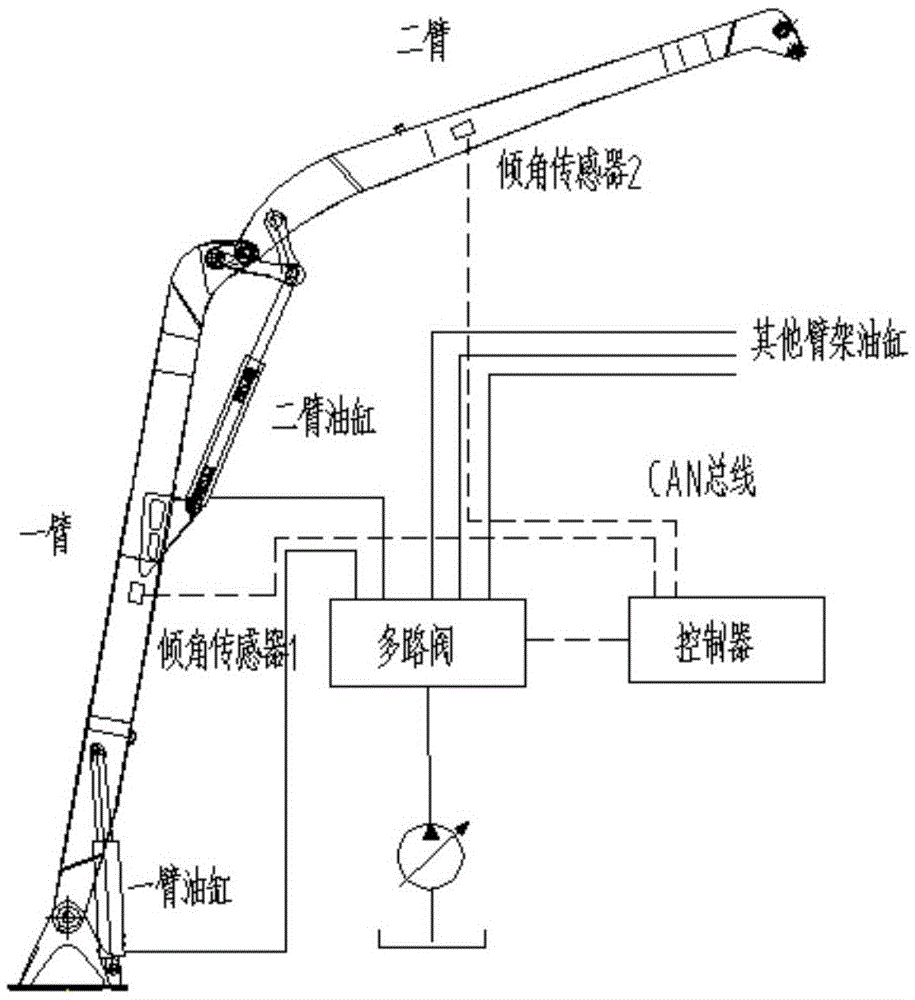
technical field [0001] The present invention relates to the technical field of construction machinery control, in particular to a method, device and system for controlling the coordinated action of multiple moving parts on construction machinery. Background technique [0002] Multi-booms often appear on construction machinery. When construction machinery is equipped with a multi-boom structure, it usually requires multiple booms to move in coordination to control the trajectory of the end of the boom. Such as figure 1 The shown pump truck is equipped with multiple booms, and the principle of controlling the coordinated movement of these multiple booms is as follows: figure 2 shown. figure 2 In the multi-boom cooperative motion control system shown, an inclination sensor 1 is set on one arm, which acts under the drive of the first arm cylinder, and an inclination sensor 2 is set on the second arm, which moves under the drive of the two arm cylinder. The two arms move tog...

Claims


Application Information

Patent Timeline
Patent Type & Authority Patents(China)
IPC IPC(8): F15B11/22F15B13/06
Inventor 赵鑫万梁王佳茜
Owner HUNAN ZOOMLION INTELLIGENT TECH
Learn More