Electromechanical integrated novel omnibearing structure wheel device

An all-in-one, new technology, applied in the directions of wheels, transportation and packaging, vehicle components, etc., can solve problems such as control failure, vibration, torque imbalance, etc., to achieve the effect of improved manufacturing process, simple control algorithm, and avoidance of high peaks

Pending Publication Date: 2018-02-23
NANCHANG UNIV
View PDF0 Cites 13 Cited by
  • Summary
  • Abstract
  • Description
  • Claims
  • Application Information

AI Technical Summary

Problems solved by technology

[0004] The advantage of the above two types of wheels is that they are compact in structure and can move in all directions. However, there are inevitably structural gaps between the driven rollers distributed on the rims of the above two types of wheel systems. In single-row applications, the wheels roll continuously. Due to the gap between the rollers on the rim when the wheel is rolling, trembling and vibration will inevitably occur. The most prominent defect is that when a single such omnidirectional wheel is combined with an ordinary universal wheel to build a mobile platform, it can only meet the requirements of X Or Y unidirectional movement requires more than four combined applications to achieve omnidirectional movement without changing the platform posture
In addition, when moving in non-X and Y directions and at a certain angle, due to the unbalanced torque generated by the movement of each wheel body component, the power of one of the motors will have a high peak value, which is prone to control failure, and the control algorithm is difficult It is relatively large, the production process is complicated and difficult, and special equipment is required to make it

Method used


Image

  • Electromechanical integrated novel omnibearing structure wheel device
  • Electromechanical integrated novel omnibearing structure wheel device

Examples


Embodiment Construction

[0015] The present invention will be further described through the following embodiments in conjunction with the accompanying drawings.

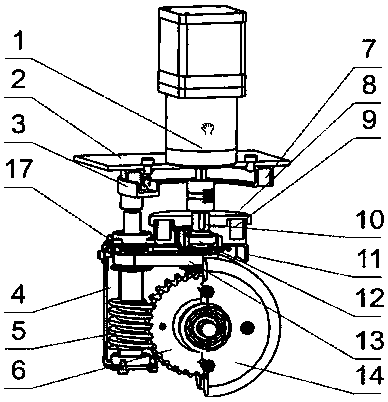
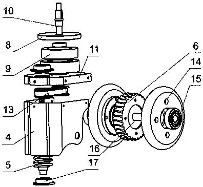
[0016] The present invention is realized like this (as figure 1 , 2 shown); the geared motor 1 is installed on the base 2, and the positioning electromagnet 7 and the positioning slip ring 3 are installed on the back of the base 1. The output shaft of the geared motor 1 is directly connected to the upper journal of the transmission shaft 10; The transmission shaft 10 is connected by a key to realize synchronous rotation; the transmission shaft 10 is fixed on the rolling bearing A12 provided in the reversing electromagnet 9 and is concentric with the position of the reversing electromagnet 9, and the lower end journal of the transmission shaft 10 is connected with the transmission pair 13 to the worm 5 transfer torque; the reversing electromagnet 9 is fixed on the wheel frame end cover 11, and the wheel frame end cover 11 is fixed on the upp...


PUM


Abstract

A new type of electromechanical integrated omnidirectional structure wheel device, including a controllable geared motor, a base for fixing the motor, a positioning electromagnet, a positioning slip ring, a reversing slip ring, a reversing electromagnet, a drive shaft wheel frame end cover, and The rolling bearing matched with the transmission shaft, the transmission pair between the transmission shaft and the worm, the upper and lower bearings for fixing the worm, the wheel frame, the worm wheel, the worm, the two wheels forming the hub, the rolling bearing B, and the axle. The invention rotates naturally and smoothly; without changing the posture of the platform, it can achieve the effect of omnidirectional movement, and the torque of each wheel is basically balanced when moving in non-X and Y directions. When multiple omnidirectional structural wheel devices are used in combination, only a single motor can be used to realize the control and drive of multiple omnidirectional structural wheel devices through mechanical serial connection, without installing a motor on each wheel. It is convenient to realize the walking functions such as autonomous navigation, positioning, and track-seeking of the platform; the production and manufacturing process has also been greatly improved, and it is convenient to manufacture without special equipment.

Description

technical field [0001] The invention belongs to the technical field of robot chassis movement, and relates to a novel wheel train device which builds a robot mobile platform and can control omnidirectional movement with its own power. Background technique [0002] At present, in the machinery industry and high-end industrial control system equipment manufacturing industry, with the development of robot technology, the wheeled mobile robot chassis represented by the omnidirectional mobile platform has been more and more widely used, and the omnidirectional mobile platform is based on Omni-directional wheels are chassis moving mechanisms for moving parts. The omnidirectional wheel is also a key component for the platform to realize omnidirectional movement. The basic principle of the existing omnidirectional wheel is that the driving wheel can roll freely along the axis of the wheel through a number of rollers on the rim of the wheel, so as to realize the driving wheel moving ...

Claims


Application Information

Patent Timeline
Patent Type & Authority Applications(China)
IPC IPC(8): B60B19/00
CPCB60B19/003
Inventor 张华赖起荣尚志军
Owner NANCHANG UNIV
Why Eureka
Try Eureka