
Oblique multi-directional displacement telescopic device

A telescopic device and multi-directional displacement technology, which is applied to bridge parts, bridges, buildings, etc., can solve the problems of high damage rate of telescopic parts, deep design reserved groove depth, and uneven expansion and contraction, so as to facilitate installation, replacement and maintenance, and improve Driving comfort, effect of reducing structural size

Pending Publication Date: 2018-03-02
尚德建设集团有限公司 +1
View PDF0 Cites 1 Cited by
  • Summary
  • Abstract
  • Description
  • Claims
  • Application Information

AI Technical Summary

Problems solved by technology

[0004] The section steel modular expansion devices currently on the market have large longitudinal expansion gaps, uneven expansion, concentrated impact force, severe vehicle jumping, fragile concrete, high damage rate of expansion parts, high manufacturing costs, and reserved slots for design. Phenomena such as depth are more prominent
Especially for suspension bridges, cable-stayed bridges, and oblique and curved bridges, due to the inevitable multi-directional displacement of the bridge structure, the defects that do not meet the requirements of lateral and multi-directional displacement have been seriously exposed during the use process
However, for cable-stayed bridges and suspension bridges with high requirements for vertical deformation and large longitudinal and lateral displacements, it is difficult for bridge modulus telescopic devices to meet the requirements for multi-directional displacements.
However, the conventional comb-tooth plate expansion joints cannot meet the vertical corner requirements of the bridge girder body.

Method used


Image

  • Oblique multi-directional displacement telescopic device
  • Oblique multi-directional displacement telescopic device
  • Oblique multi-directional displacement telescopic device

Examples


Embodiment Construction

[0024] The technical solutions of the present invention will be clearly and completely described below in conjunction with the embodiments. Apparently, the described embodiments are only some of the embodiments of the present invention, not all of them. Based on the embodiments of the present invention, all other embodiments obtained by persons of ordinary skill in the art without creative efforts fall within the protection scope of the present invention.

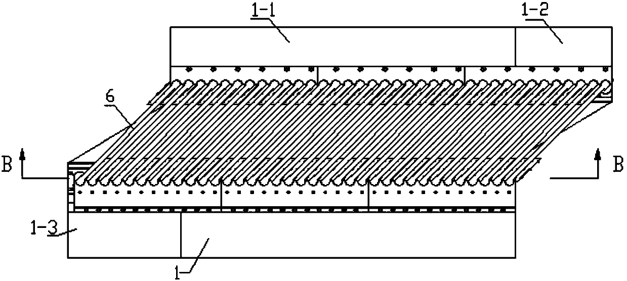
[0025] Oblique multi-directional displacement expansion device, including sliding end displacement device, fixed end displacement device, seam-spanning beam 6, and sealing device; such as Figure 1-2 As shown, the sliding end displacement device and the fixed end displacement device are respectively installed on the opposite sliding end beam body 1 and the fixed end beam body 1-1, and the sliding end beam body 1 is provided with a sliding end beam body Bracket 1-3, the fixed-end beam body 1-1 is provided with a fixed-end be...


PUM


Abstract

The invention discloses an oblique multi-directional displacement telescopic device which comprises a sliding end displacement device, a fixed end displacement device and a joint crossing girder, wherein two ends of the joint crossing girder are mounted on the sliding end displacement device and the fixed end displacement device; the sliding end displacement device comprises a sliding end base, arear seat, a guide pressure plate, a guide sleeve rail, a rotary ball crown, a rotary ball seat, a sliding end front guide sleeve and a cover plate; the guide pressure plate is fixed with the slidingend base, and the guide sleeve rail, the rotary ball crown, the rotary ball seat and the sliding end front guide sleeve are limited on the sliding end base; the cover plate is connected and fixed withthe guide sleeve rail and is in contact with the joint crossing girder and the rear seat; the fixed end displacement device is composed of a fixed end base, a fixed end front guide sleeve, a fixed end rear guide sleeve, a fixed end cover pressure plate, a rotary ball crown and a rotary ball seat; and the fixed end cover pressure plate tightly presses the joint crossing girder with the rotary ballcrown and the rotary ball seat. The device disclosed by the invention improves the driving comfort, reduces the structure size of an expansion joint mounting groove of a bridge, reduces vibration andnoise, and is convenient to mount, replace and maintain.

Description

technical field [0001] The invention belongs to the technical field of bridge expansion and contraction, and in particular relates to an oblique multidirectional displacement expansion device. Background technique [0002] Expansion devices are required on the bridge to meet the expansion and contraction requirements of the bridge. The telescopic device is a key part of the bridge components and plays an important role in realizing the bridge function. Common bridge expansion devices include plate rubber expansion devices, steel modular expansion devices, and comb-tooth plate expansion devices. During the construction and operation of the bridge, it will be subjected to vehicle loads, shrinkage and creep of the bridge's own materials, foundation settlement, wind load, etc., causing deformation of the bridge beam end. [0003] However, the currently used telescopic devices can only meet the horizontal telescopic adjustment, and cannot meet the vertical displacement deformat...

Claims


Application Information

Patent Timeline
Patent Type & Authority Applications(China)
IPC IPC(8): E01D19/06
CPCE01D19/06E01D19/062
Inventor 徐彬张春孙鹏方家琛胡建华
Owner 尚德建设集团有限公司
Learn More