

Unit beam type multidirectional displacement telescopic device
A multi-directional displacement and telescopic device technology, which is applied in bridges, bridge parts, bridge construction, etc., can solve the problems of high damage rate of telescopic parts, poor bending resistance, deep design reserved groove depth, etc., so as to avoid vehicle jumping and noise generation, improve structural safety performance, and improve the effect of material utilization layout
- Summary
- Abstract
- Description
- Claims
- Application Information
AI Technical Summary
Problems solved by technology
Method used
Image

Examples
Embodiment Construction
[0033] The technical solutions of the present invention will be clearly and completely described below in conjunction with the embodiments. Apparently, the described embodiments are only some of the embodiments of the present invention, not all of them. Based on the embodiments of the present invention, all other embodiments obtained by persons of ordinary skill in the art without creative efforts fall within the protection scope of the present invention.
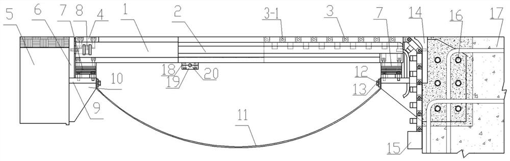
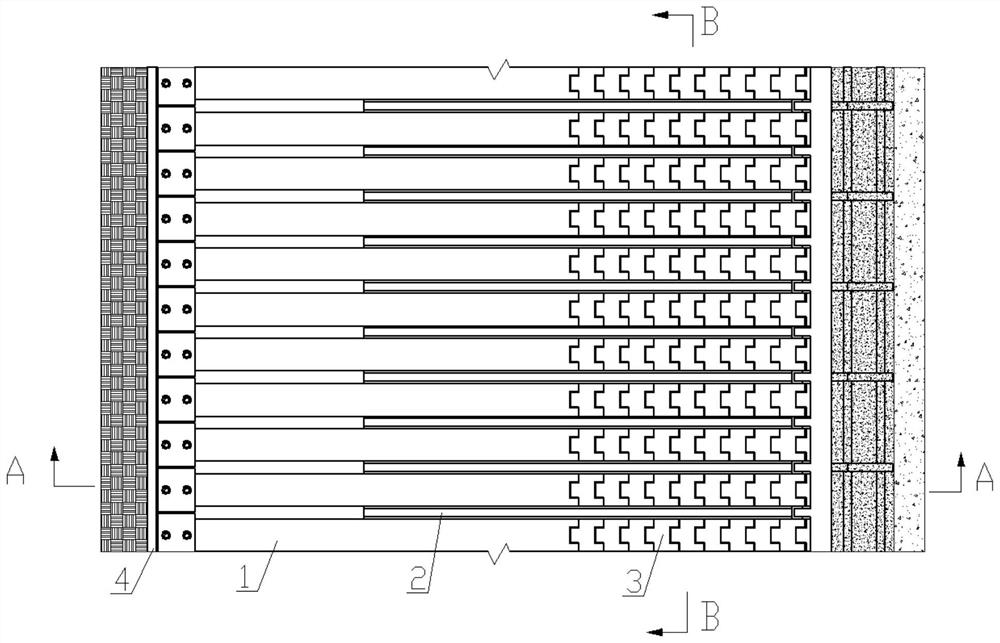
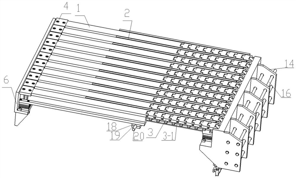
[0034] like Figure 1-10 As shown, the present invention is a unit beam type multi-directional displacement telescopic device, including a unit beam, a shock-absorbing multi-directional displacement support 7, an undercut panel 3, a concrete end support bracket 14, a cable device, and a limit device 8 . Water-stopping device, the unit beam is divided into a fixed unit beam 2 and a telescopic unit beam 1, and the fixed unit beam 2 is installed on the shock-absorbing multi-directional displacement support 7 of the concrete en...
PUM
 Abstract
Description
Claims
Application Information