A method, device and system for detecting wiring of a component inverter
What is AI technical title?
AI technical title is built by Patsnap AI team. It summarizes the technical point description of the patent document.
A detection method and inverter technology, applied in the direction of electrical connection testing, etc., can solve the problems of inverter damage, wrong connection, reverse connection of input terminals, etc.
Active Publication Date: 2020-07-07
SUNGROW POWER SUPPLY CO LTD
View PDF7 Cites 0 Cited by
Summary
Abstract
Description
Claims
Application Information
AI Technical Summary
This helps you quickly interpret patents by identifying the three key elements:
Problems solved by technology
Method used
Benefits of technology
Problems solved by technology
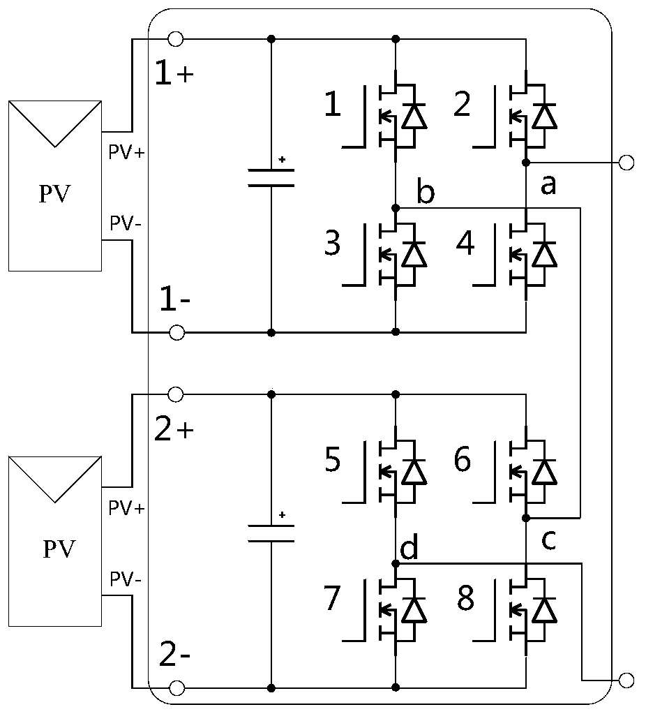
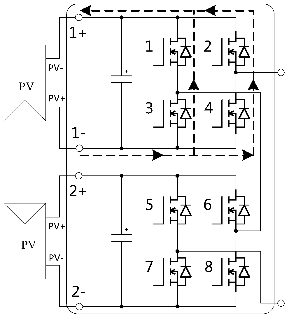
[0005] However, the structure and size of the input terminal of the sub-inverter are basically the same, and the structure and size of the output terminal are also basically the same. During actual production and installation, the input terminal is reversed, wrongly connected, or the output terminal is reversed. phenomenon, which in turn will cause damage to the inverter and cannot generate electricity normally.
Method used
Image
Click on the blue label to locate the original text in one second.
Reading with bidirectional positioning of images and text.
Examples
Embodiment 1
[0110] 1) Assuming that the photovoltaic power generation system including 12 component inverters cascaded is installed, the main control interface board of the system can communicate with each component inverter, and the corresponding DC bus of each component inverter can be obtained The voltage is 30V, and the 12 component inverters are divided into 12 groups, that is, each sub-inverter group includes a sub-inverter.
[0111] 2) The MCU of the main control interface board of the system sends instructions through communication to control one sub-inverter group to output positive level, and the other 11 sub-inverter groups output 0 level.
[0112] It should be noted that this is just an example. For example, it is also possible to control 3 sub-inverter groups to output positive levels, 5 sub-inverter groups to output 0 level, and other sub-inverter groups to output negative levels. Or other combinations are also possible.
[0113] 3) The main control interface board of the s...
Embodiment 2
[0116] 1) Assuming that the photovoltaic power generation system including 12 component inverters cascaded is installed, the main control interface board of the system can communicate with each component inverter, and the corresponding DC bus of each component inverter can be obtained The voltage is 30V, and the 12 component inverters are divided into 6 groups, that is, each sub-inverter group includes 2 sub-inverters.
[0117] 2) The MCU of the main control interface board of the system sends instructions through communication to control the three sub-inverter groups to output positive levels, and the other sub-inverter groups to output 0 level.
[0118] It should be noted that this is just an example. For example, it is also possible to control one sub-inverter group to output a positive level, three sub-inverter groups to output a 0 level, and the remaining sub-inverter groups to output a negative level. Or other combinations are also possible.
[0119] 3) The main control...
PUM
Abstract
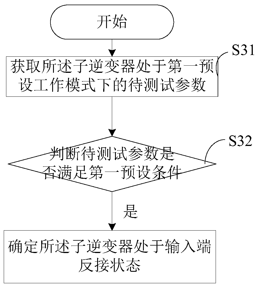
The invention provides a component type inverter wiring detection method applied to a component type inverter. The component type inverter includes at least one sub inverter. According to the method,a to-be-tested parameter of the sub inverter in a first preset working mode is obtained; whether the to-be-tested parameter meets first preset conditions is determined; and if so, the sub inverter isdetermined to be in an inversed input terminal connection state, wherein the first preset conditions include conditions that the direct-current input voltage of the sub inverter is lower than a firstpreset voltage threshold, and / or the direct-current input current of the sub inverter is lower than a first preset current threshold, and / or the input temperature of the sub inverter is high than a first preset temperature threshold. Therefore, the invention provides a wiring detection method capable of testing the wiring situation. Besides, the invention also provides a method for testing wrong connection of an input terminal of an inverter and inversed connection of an output terminal of an inverter. When a wrong connection situation of a wiring terminal occurs, alarming is carried out.
Description
technical field [0001] The invention relates to the technical field of photovoltaic power generation, in particular to a method, device and system for detecting wiring of a component inverter. Background technique [0002] With the continuous development of science and technology, photovoltaic power generation system has also been developed rapidly. Usually, in the current photovoltaic power generation system, a plurality of photovoltaic modules are connected in series to form a photovoltaic string, and then the photovoltaic strings are connected in parallel to form a photovoltaic array. Converted alternating current is sent to the grid. [0003] In a conventional photovoltaic power generation system, a string photovoltaic power generation system usually has multiple MPPTs. However, factors such as shadow occlusion, component parameter differences, component aging attenuation and other factors will cause the series and parallel mismatch of components, resulting in the loss...
Claims
Application Information
Patent Timeline
Application Date:The date an application was filed.
Publication Date:The date a patent or application was officially published.
First Publication Date:The earliest publication date of a patent with the same application number.
Issue Date:Publication date of the patent grant document.
PCT Entry Date:The Entry date of PCT National Phase.
Estimated Expiry Date:The statutory expiry date of a patent right according to the Patent Law, and it is the longest term of protection that the patent right can achieve without the termination of the patent right due to other reasons(Term extension factor has been taken into account ).
Invalid Date:Actual expiry date is based on effective date or publication date of legal transaction data of invalid patent.

