Vacuum solar steam heat collection tube, steam heat collection plate, solar water-heating air conditioner device

A technology of solar steam and heat collecting tubes, which is applied in the fields of solar heat collecting elements, hot water devices and air conditioning devices, and can solve problems such as large resistance, short transportation distance and narrow application range

Inactive Publication Date: 2008-07-23
喜春野
View PDF1 Cites 8 Cited by
  • Summary
  • Abstract
  • Description
  • Claims
  • Application Information

AI Technical Summary

Problems solved by technology

Obviously, there are many limitations and deficiencies in this vacuum heat collecting tube: First, there is a large amount of water in the tube, large heat capacity, slow temperature rise, low water temperature, and is limited to producing hot water below 100 degrees, and generally works in the range of 40 degrees to 90 degrees It is difficult to adapt to many target fields, and its

Method used


Image

  • Vacuum solar steam heat collection tube, steam heat collection plate, solar water-heating air conditioner device
  • Vacuum solar steam heat collection tube, steam heat collection plate, solar water-heating air conditioner device
  • Vacuum solar steam heat collection tube, steam heat collection plate, solar water-heating air conditioner device

Examples


Embodiment Construction

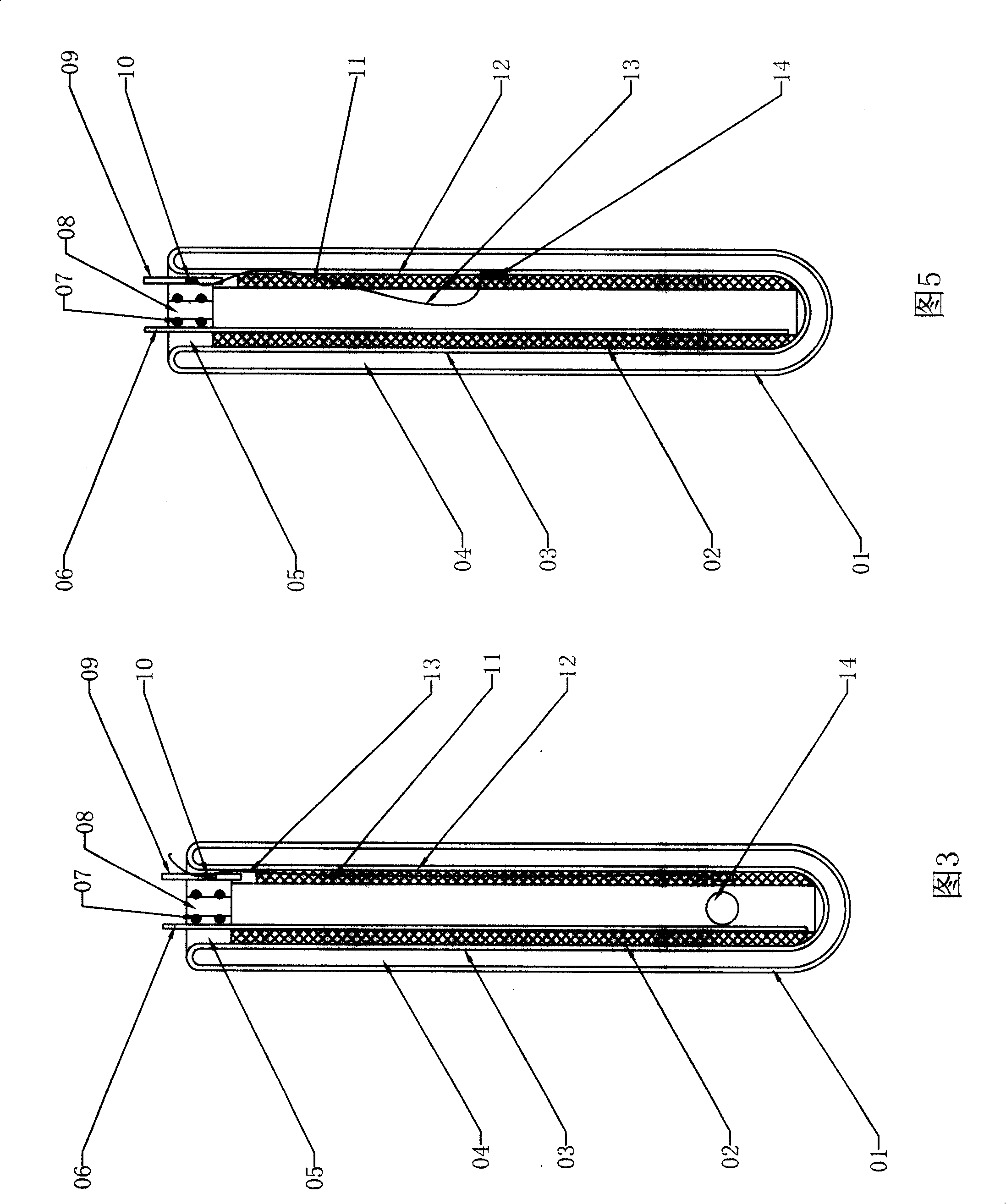
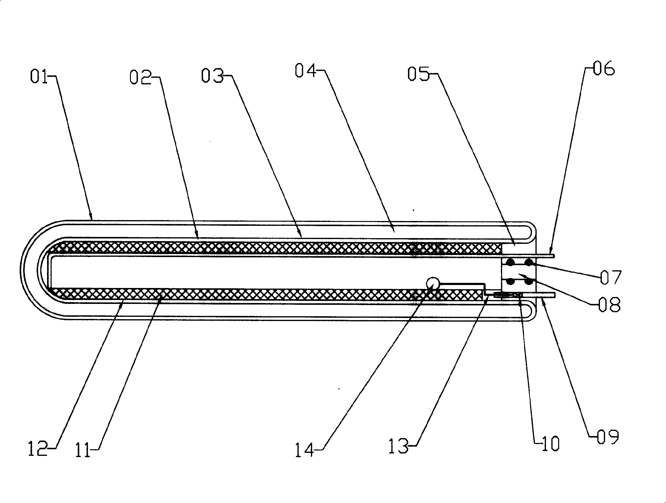
[0027] In the vacuum solar steam heat collection tube shown in Figure 1, one end of the transparent outer tube (01) is closed, and it is set on the outside of another inner tube (02) that is also closed at the same end, and its open ends are fused and sealed, between the two sleeves A vacuum interlayer (04) is formed between them, the outer surface of the inner tube (02) is coated with a selective solar absorbing coating (03), and a sealing end cover (05) is provided on the open end of the inner tube (02), and a sealing tape is provided on it. The exhaust port (08), liquid inlet pipe (09) and spare pipe (06) of (07), the liquid inlet pipe (09) is connected with the float regulating valve (10) and the liquid outlet is introduced into the core pipe (11) , the inner wall of the inner tube (02) is concentrically provided with a multi-gap capillary core tube (11), the core tube (11) is filled with liquid medium, and an annular liquid film (12) is formed on the wall of the inner tube...


PUM


Abstract

The invention discloses a vacuum solar vapor heat-collecting tube, a vapor heat-collection plate formed by the vacuum solar vapor heat-collecting tube, and a vapor hot water air conditioner, which is characterized in that a sealing end cover is positioned at the open end of a common vacuum solar heat-collecting tube; a plurality of vapor exhaust ports, a plurality of liquid inlet tubes and a standby pipe are positioned on the sealing end cover; a homocentric core tube is positioned in the intracavity of the inner pipe; a liquid membrane gap is formed between the core tube and the inner pipe; the outlet of the liquid inlet tube is introduced into the liquid membrane gap; an adjusting valve, controlled by liquid level in the pipe or the temperature of inner pipe wall, is connected in series with the liquid inlet tube; a plurality of heat-collecting tubes are positioned in parallel in a frame; the back face of the frame is lined with a reflector; a light transmission plate is positioned on the front face of the frame; the vapor exhaust ports converge in a vapor exhaust header; the liquid inlet tube converges in a liquid return header; the vapor exhaust header and the liquid return header are positioned in the frame and simultaneously the heat is preserved; the interfaces of the headers expose to the outside, forming a vapor heat-collection plate; the vapor exhaust header and the liquid return header of the vapor heat-collection plate are connected with a through hole vapor absorber and a water outlet at the bottom part of a water tank by a vapor transportation pipe and a liquid return pipe, forming a water heater; an absorption-type air conditioner is connected in series with the vapor transportation pipe; a steam boiler is connected in parallel between the vapor transportation pipe and the liquid return pipe, forming the hot water air conditioner.

Description

technical field [0001] The invention belongs to the technical field of solar photothermal application, and relates to a solar heat collecting element, in particular to a solar heat collecting element which is vacuum-insulated and capable of rapidly generating steam. The present invention also relates to a flat-plate solar heat-collecting component composed of the heat-collecting element, and a water heater and an air-conditioning device composed of the same. Background technique [0002] At present, the heat collecting elements widely used in solar water heating systems are mostly originated from Chinese patent 95215311.4, that is, "a new type of all-glass vacuum solar heat collecting tube", which consists of a transparent outer tube closed at one end and an inner tube closed at the same end. On the outside, the other open end is fused and sealed to form a vacuum insulation interlayer between the two tubes. The outer surface of the inner tube is coated with a solar selective...

Claims


Application Information

Patent Timeline
IPC IPC(8): F24J2/05F24J2/24F25B27/00F24S10/40F24S10/70
CPCY02E10/44
Inventor 喜春野
Owner 喜春野
Why Eureka
Try Eureka