

Single-stage integrated drying equipment
A drying equipment, single-stage technology, applied in the device, printing, printing machine and other directions of coating liquid on the surface, can solve the problems of troublesome installation and transportation, large energy consumption for heating, affecting the quality of product processing, etc. Simple and compact, the drying effect is improved, and the drying process is perfect.
- Summary
- Abstract
- Description
- Claims
- Application Information
AI Technical Summary
Problems solved by technology
Method used
Image

Examples
specific Embodiment 1
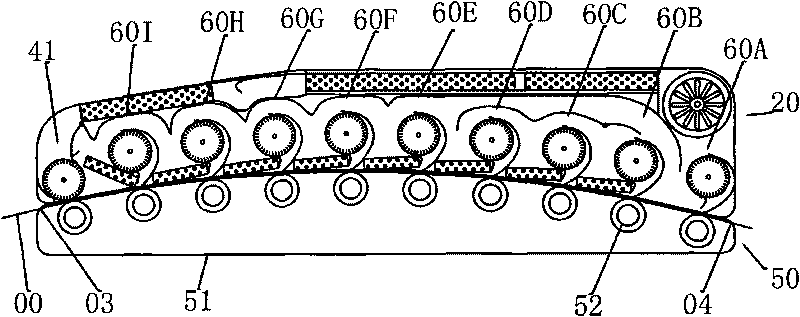
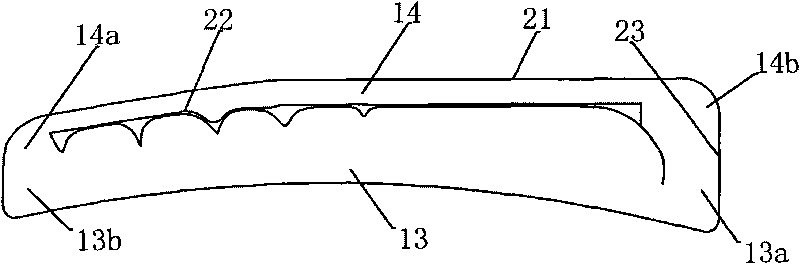
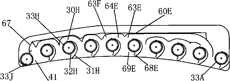
[0060] Figure 1 to Figure 7 Constitute the specific embodiment 1 of the present invention.
[0061] This embodiment is suitable for drying equipment for water-based ink printing machines.
[0062] Figure 10 A schematic diagram of the heat pipe heat exchanger provided by the present invention is provided.
[0063] The corresponding relationship between component names and reference signs in each drawing is shown in Table 1.
[0064] Table 1: Correspondence between part names and reference signs
[0065] 00--Print 10--Oven 20--Oven cover
01--Fresh air inlet 11--Intake cavity 21--Outer cover parts
02--exhaust gas outlet 12--exhaust chamber 22--baffle parts
03--Print product entrance 13--Drying chamber 23--Frame parts
04--Print product export 14--Recycling cavity 24--Front beam
08--Protection gas injection 16--Low temperature section 25--Rear beam
Inlet 17--Middle temperature section 26--Left wall panel
18--high tempe...
specific Embodiment 2
[0100] This embodiment is suitable for drying equipment for solvent printing presses operating under extreme conditions.
[0101] Figure 8 , Figure 9 It is the accompanying drawing of the specific embodiment 2 of the present invention, which embodies the difference between this embodiment and the specific embodiment 1 in that:
[0102] A protective gas injection port 08 is added for injecting nitrogen to discharge air, completely destroying the explosion conditions of organic solvent vapor. The control device 70 includes an oxygen concentration sensor and an electromagnetic gas valve, which are used to control the injection amount of the protective gas to ensure that the oxygen content is lower than the allowable value. Both the print entrance 03 and the print exit 04 take measures to increase wind resistance to reduce gas leakage. Under the protection of the above safety measures, the concentration of solvent vapor in the oven can be increased to about 5%, which facilita...
PUM
 Abstract
Description
Claims
Application Information