Method for producing pipe steel

A pipe steel and casting machine technology, applied in temperature control, metal rolling, etc., can solve the problems of limited flexible manufacturing and affecting tissue development, and achieve the effect of high strength and toughness

Active Publication Date: 2014-07-30
SMS DEMAG AG
View PDF9 Cites 0 Cited by
  • Summary
  • Abstract
  • Description
  • Claims
  • Application Information

AI Technical Summary

Problems solved by technology

[0006] Disadvantageously, the processing devices and methods known in advance are not optimally suited to react flexibly to the corresponding initial conditions and requirements when processing microalloyed steels, especially tube steels, in order to Largely freely selectable temperature profiles (Temperaturprofil) for machining these steel types
It is thus not possible to optimally control and influence the microstructure development in the steel
Therefore, the flexible production of the mentioned steels with regard to their chemical composition and dimensions (Abmessung) is limited

Method used


Image

  • Method for producing pipe steel
  • Method for producing pipe steel
  • Method for producing pipe steel

Examples


Embodiment Construction

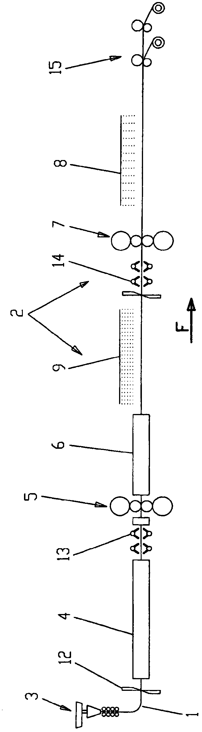
[0056] exist figure 1 A plant 2 for casting and rolling steel pipe (according to API specification 5L) in one line is depicted in side view. It has a casting machine 3 (vertical casting plant or curved casting plant) in which slabs 1 are produced in a known manner by continuous casting. Typical dimensions of the slab may be a thickness between 50 and 150 mm and a width between 900 and 3000 mm. In the conveying direction F, the casting machine 3 is followed by a first melting furnace 4, a roughing train for rolling slabs (where only a single roughing stand 5 is shown (sometimes several roughing stands are also provided)) , a second melting furnace 6 , a finishing train for rolling slabs or strips (of which only a single finishing stand 7 is shown (mostly a plurality of finishing stands are provided)) and a cooling section 8 .

[0057] There are also additional elements which are not important or only secondary in terms of temperature control. A shear 12 is arranged between t...


PUM


Abstract

The invention relates to a method for the production of microalloyed steels, in particular pipe steels, wherein a cast slab (1) passes through a device (2) in the conveying direction (F) of the slab (1) at The sequence has a casting machine (3), a first melting furnace (4), at least one roughing stand (5), a second melting furnace (6), at least one finishing stand (7) and a cooling section (8), wherein the The method comprises: a) defining for the slab (1) a desired temperature profile on its progress through the device (2); b) applying at least one influence for tempering the slab (1) according to the defined temperature profile The temperature-influencing elements (9, 10) are positioned in the production line (L) of the plant (2), wherein the temperature-influencing elements (9, 10) are introduced into the first melting furnace (4) and the at least one roughing stand (5) and/or between the second melting furnace (6) and the at least one finishing stand (7); c) producing slabs (1) in equipment (2) designed in such a way that the at least one temperature-influencing The elements (9, 10) are operated such that the defined temperature profile is at least largely maintained. Furthermore, the invention relates to a plant for the manufacture of microalloyed steels.

Description

technical field [0001] The invention relates to a method for manufacturing microalloy steel, especially pipe steel method, wherein the cast slab (Bramme) passes through a plant which has in this order a casting machine, a first melting furnace, at least one roughing stand (Vorwalzgerüst), a second melting furnace, at least one A finishing stand and cooling section (Kuehlstrecke). Furthermore, the invention relates to a plant for the manufacture of microalloyed steels. Background technique [0002] Various possibilities are described in the prior art for the production of strips, which work according to this type of method. Reference is made, for example, to documents US 2005 / 0115649A1, WO 2009 / 012963A1, WO 2007 / 073841A1, WO 2009 / 027045A1, EP 0 611 610B1 and EP 1 860 204A1. [0003] The established method is thermomechanical rolling. Recently, microalloyed steels have become more and more important. In this context, tubular steel (according to API specification 5L) is o...

Claims


Application Information

Patent Timeline
Patent Type & Authority Patents(China)
IPC IPC(8): C21D8/02B22D11/12
CPCB21B1/46B21B37/74B22D11/1206C21D8/0226C21D8/021B21B1/463C21D8/0215B22D11/12C21D8/02
Inventor J·赛德尔J·奥勒特
Owner SMS DEMAG AG
Why Eureka
Try Eureka