Plant state displaying apparatus, plant state displaying system, and method of displaying plant state

A state display and workshop technology, applied in the general control system, control/regulation system, test/monitoring control system, etc., can solve the problems of signs and other display becoming smaller, information display, etc.

Active Publication Date: 2018-03-23
YOKOGAWA ELECTRIC CORP
View PDF9 Cites 1 Cited by
  • Summary
  • Abstract
  • Description
  • Claims
  • Application Information

AI Technical Summary

Problems solved by technology

However, it is conceivable that as the number of instruments increases, the display of symbols and the like becomes smaller, so it is difficult to grasp the changing trend of the state quantity at a glance
In addition, in the technique disclosed in the above-mentioned Patent Document 2, information obtained from an instrument having a sensor is basically displayed, and information on a part without a sensor (for example, a piping part) cannot be displayed.
[0008] In this way, in the techniques disclosed in Patent Documents 1 and 2 above, for example, it is sometimes difficult to display the plant status of the entire system of the plant in a manner that can be grasped at a glance, that is, it is difficult to accurately grasp the state of the plant in a short time. Any range of states to display

Method used


Image

  • Plant state displaying apparatus, plant state displaying system, and method of displaying plant state
  • Plant state displaying apparatus, plant state displaying system, and method of displaying plant state
  • Plant state displaying apparatus, plant state displaying system, and method of displaying plant state

Examples


no. 1 Embodiment approach

[0048]

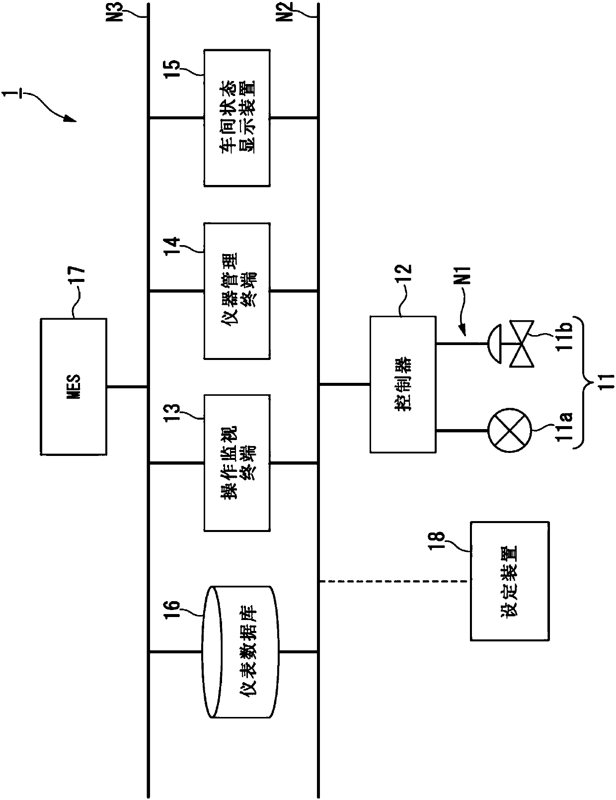
[0049] figure 1 It is a block diagram showing the overall configuration of the process control system according to the first embodiment. Such as figure 1 As shown, the process control system 1 has a field instrument 11, a controller 12, an operation monitoring terminal 13, an instrument management terminal 14, a workshop status display device 15, an instrument database 16, and an MES (Manufacturing Execution System: Manufacturing Execution System) 17. Under the management of the controller 12, the field instrument 11 is controlled, thereby performing process control. In addition, the setting device 18 in the figure is a device for performing various settings for devices (for example, field devices 11 ) installed in the process control system 1 .

[0050] Such a process control system 1 is constructed in a workshop, a factory, etc. (hereinafter, in case of collectively referring to them, simply referred to as "workshop"). Here, as the above-mentioned workshops, in...

no. 2 Embodiment approach

[0113]

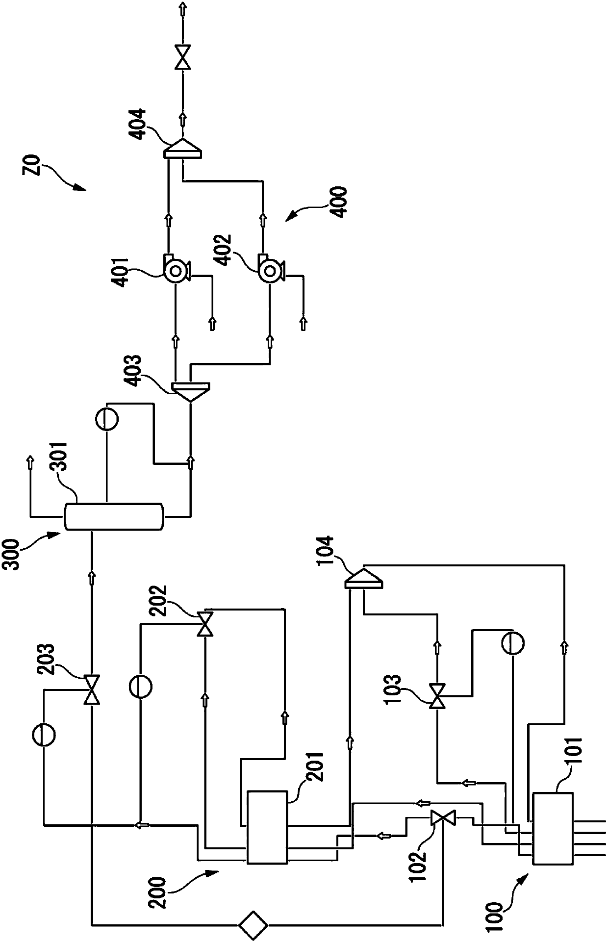
[0114] Figure 8 It is a block diagram showing the overall configuration of the process control system according to the second embodiment. Figure 8 The process control system 1 shown is relative to figure 1 The shown process control system 1 has a structure in which a plant performance evaluation system 30 (simulation device) is added. This plant performance evaluation system 30 has a static simulator and a dynamic simulator (or a static simulator and a tracking simulator), and simulates a plant.

[0115] The above-mentioned static simulator is a simulator that simulates the steady state of the equipment constituting the plant using a static model (a model obtained by modeling the steady state of the equipment constituting the plant). In addition, the above-mentioned dynamic simulator is performed using a dynamic model (a model obtained by modeling the dynamic state (unsteady state) of a plant in consideration of the mutual relationship of the instruments constit...


PUM


Abstract

A plant state displaying apparatus displaying information representing a state of a plant according to the present invention includes a generator configured to acquire plant information from at leastone of devices, apparatuses, and facilities installed in the plant, calculate a state value representing the state of the plant using the plant information, and generate a plant state diagram in whichat least one of a color and a density of at least one of devices, apparatuses, and facilities from which the plant information is acquired is changed according to magnitude of the state value, and adisplay configured to display the plant state diagram generated by the generator as the information representing the state of the plant.

Description

technical field [0001] The invention relates to a workshop state display device, a workshop state display system and a workshop state display method. [0002] This application claims priority based on Japanese Patent Application No. 2016-182182 for which it applied in Japan on September 16, 2016, and uses the content here. Background technique [0003] In workshops, factories, etc., a variety of instruments, devices, and equipment are installed and used together. The number of instruments and the like installed in a workshop roughly increases or decreases according to the scale of the workshop, but it is difficult to monitor the many instruments installed in a large-scale workshop. Since the workshop is used for a long time (for example, 30 years or more), it is necessary to properly repair (or maintain) the above-mentioned instruments and the like installed in the workshop to maintain the performance of the workshop for a long time. [0004] In order to properly monitor a...

Claims


Application Information

Patent Timeline
Patent Type & Authority Applications(China)
IPC IPC(8): G07C3/00G06F17/30G06Q50/04
CPCG06F16/9038G06Q50/04G07C3/005G05B23/0267G05B23/0205G05B23/0221G05B23/027G05B23/0272G05B2219/24177
Inventor 石建信山本光浩日高佳久江间伸明
Owner YOKOGAWA ELECTRIC CORP
Why Eureka
Try Eureka