Method for monitoring factory state and factory monitoring device

A monitoring device and factory technology, applied in the direction of electrical testing/monitoring, testing/monitoring control systems, instruments, etc., can solve problems such as installation space and cable construction, difficulty in factory monitoring, new costs and redesign, and reduce operating costs cost effect

Inactive Publication Date: 2005-02-16
HITACHI LTD
View PDF1 Cites 2 Cited by
  • Summary
  • Abstract
  • Description
  • Claims
  • Application Information

AI Technical Summary

Problems solved by technology

[0004] However, in order to facilitate instant monitoring or operation and improve monitoring performance, it is required to increase the amount of information displayed on the screen. For this purpose, it is necessary to add a CRT device for monitoring, or a multi-screen corresponding device for a large-screen device, and a new monitoring device. Disks, etc., easy to form the purchase of high-priced equipment
[0005] The increase of equipment sometimes causes incidents such as setting up space and cable work, requiring new expenses and redesign
The small-person factory monitoring method aimed at reducing the operating cost by reducing the number of operators. Since a small number of operators are used to implement factory monitoring and operation, the burden of operator monitoring and operation is increased. In large factories such as power stations, Since there are many monitoring points such as the number of pipes and sensors, it is difficult to monitor the factory with a small number of people

Method used


Image

  • Method for monitoring factory state and factory monitoring device
  • Method for monitoring factory state and factory monitoring device
  • Method for monitoring factory state and factory monitoring device

Examples


Embodiment Construction

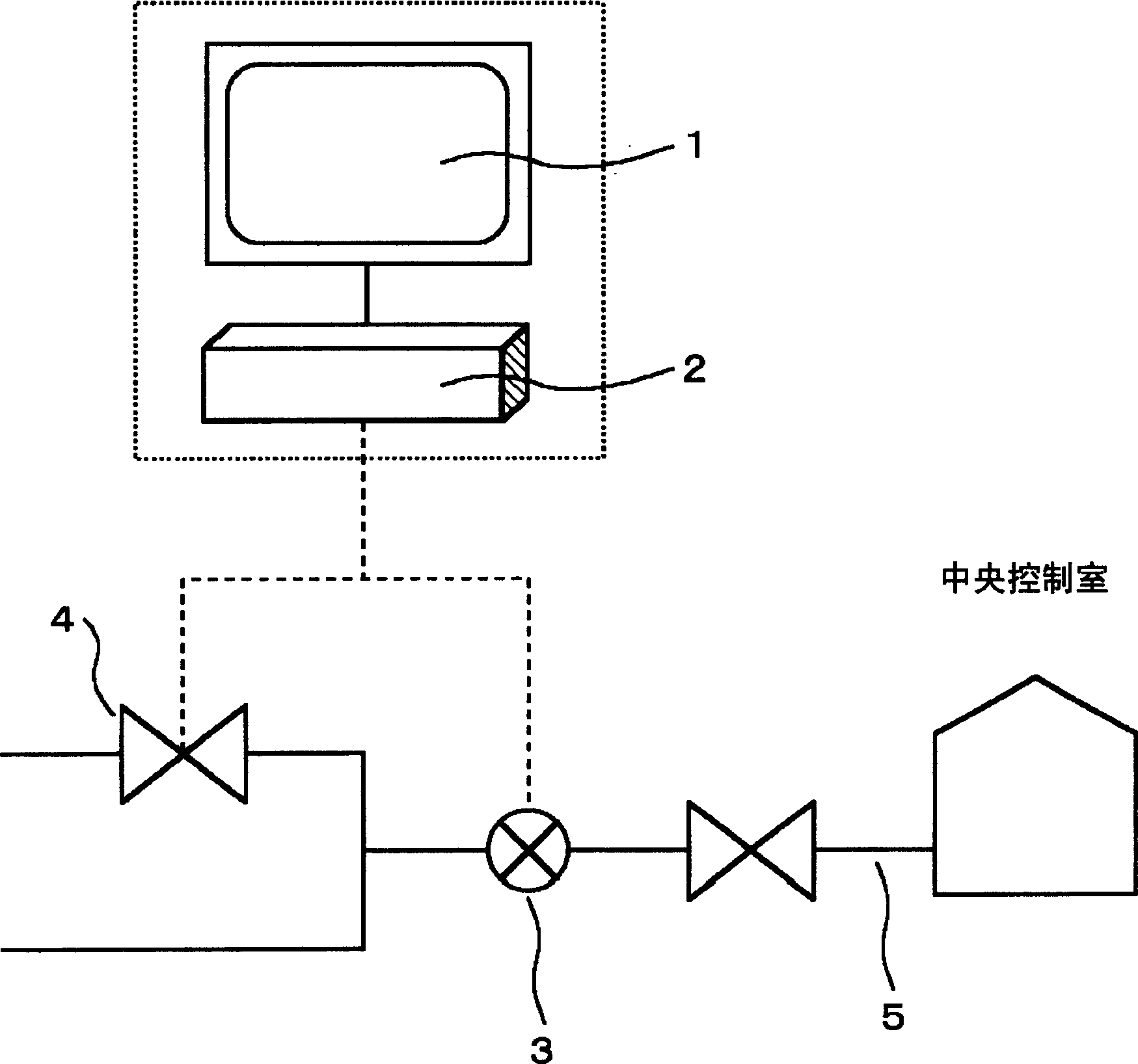
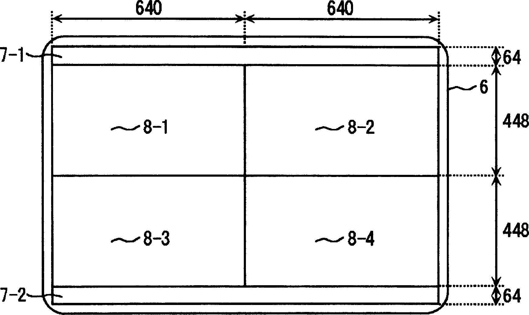
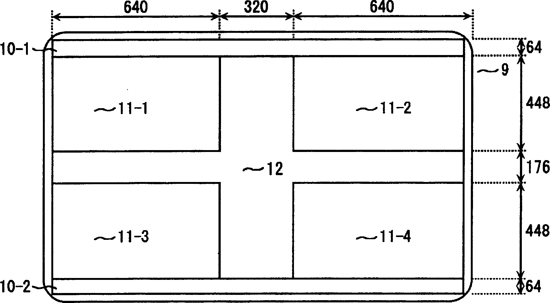
[0023] Although an example in which the present invention is extended to monitor on four screens is shown, the display screen may be divided into two screens. Similarly, of course, the display screen may be divided into 5 screens, 6 screens, or more than 4 screens. Embodiments are described in detail using drawings. Hereinafter, it demonstrates concretely using drawing. figure 1 An example of system configuration for implementing the present invention is shown. The factory monitoring device for monitoring and operating factory information includes: display device control device 2, which maintains the functions of software and database providing information such as piping system diagrams and alarm indications; display device 1, for transmitting these information to operators A visual display is performed; a sensor 3 which transmits the state of the plant as electronic information to a plant monitoring device; and a pipe 5 which connects an operating terminal which transmits t...


PUM


Abstract

To efficiently display a plant state. For example, a plant state such as the connection state of a piping system is displayed on a display picture so as to be monitored by an operator. The display picture is divided into three areas(preferably, four areas). The area interposed between the respective areas is used as a gap area, and for example, the connection of a piping system is emphasis-displayed in the gap area so that the display of the gap area can be associated with the display of the other areas. Thus, it is possible to visually and efficiently display the plant state.

Description

technical field [0001] The present invention relates to a factory state monitoring method and a factory monitoring device. Background technique [0002] For the convenience of operation and monitoring of factory information, central monitoring room, control room, guardhouse and other places where factory information is centrally managed, centrally set up operators, and set up monitoring CRT devices and large-scale display devices. These display devices have the function of providing information such as piping system diagrams and alarm indications for displaying plant status. Such a technique is described, for example, in JP-A-5-12585. [0003] Since the operator needs to monitor and operate instantaneously, the monitoring technology of dividing the display screen into four screens is known in the factory monitoring equipment. In addition, even if the size of the display device for providing information changes, the ratio of the size per screen in the 4-screen monitoring me...

Claims


Application Information

Patent Timeline
Patent Type & Authority Applications(China)
IPC IPC(8): G06F3/048G05B23/00G05B23/02G06F3/00G06F3/0484
Inventor 村上正博
Owner HITACHI LTD
Why Eureka
Try Eureka