Single-stage boost inverter and control method thereof

An inverter and single-stage technology, which is applied in the field of single-stage boost inverter and its control, can solve the problems of increasing circuit volume, low DC bus voltage, and reducing inverter efficiency, etc.

Active Publication Date: 2018-03-23
合肥龙智机电科技有限公司
View PDF4 Cites 18 Cited by
  • Summary
  • Abstract
  • Description
  • Claims
  • Application Information

AI Technical Summary

Problems solved by technology

In 2002, Peng Fangzheng proposed the Z-source inverter, which solved some shortcomings of the traditional voltage source inverter. The Z-source inverter uses the controllable direct connection of the upper and lower bridge arm power switch tubes to increase the DC bus voltage on the input side of the inverter. , so as to increase the output AC voltage, but this inverter topology is more complex, there is a start-up shock oscillation, the DC bus voltage is lower than the capacitor voltage, and the voltage gain is limited by the direct duty cycle and modulation ratio, etc., which is far from practical application. for further study
Its disadvantage is that the starting point of the inverter is to reduce the leakage current in the voltage conversion of the photovoltaic array. There are many switching devices, which increases the volume of the circuit, and 2 / 3 of the switching devices work at high frequency. The performance requirements of switching devices are high, and the loss is large, which reduces the efficiency of the inverter

Method used


Image

  • Single-stage boost inverter and control method thereof
  • Single-stage boost inverter and control method thereof
  • Single-stage boost inverter and control method thereof

Examples


Embodiment 1

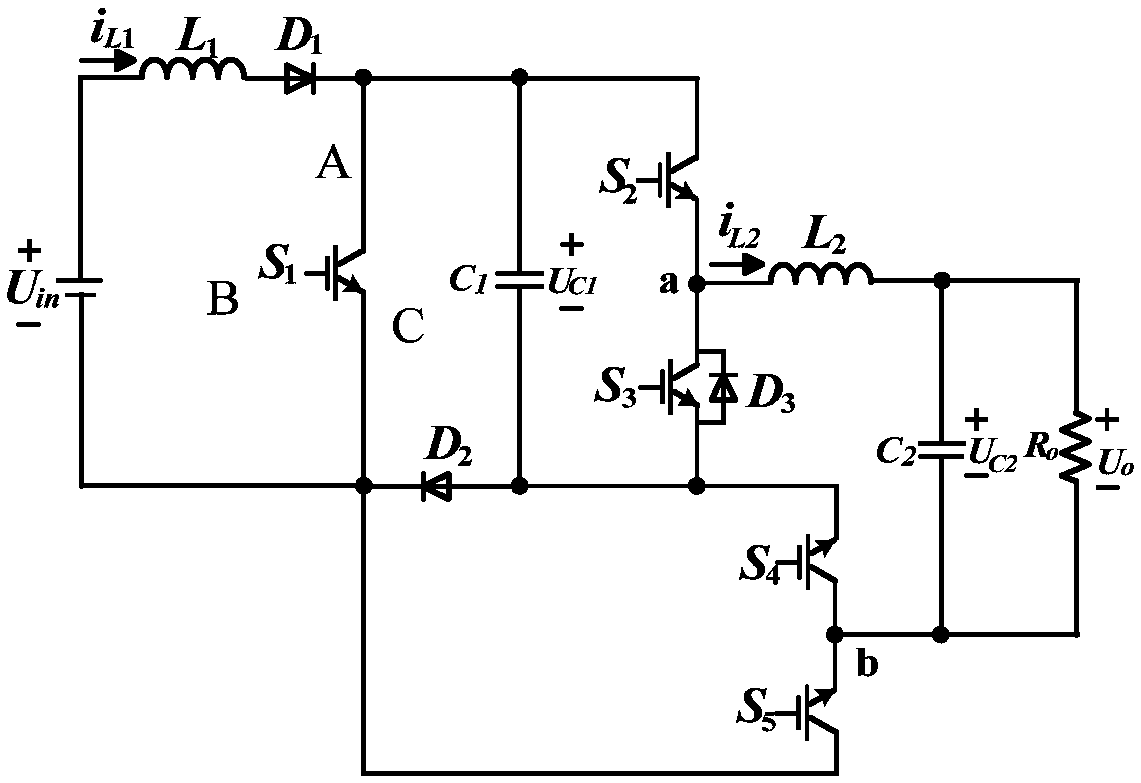
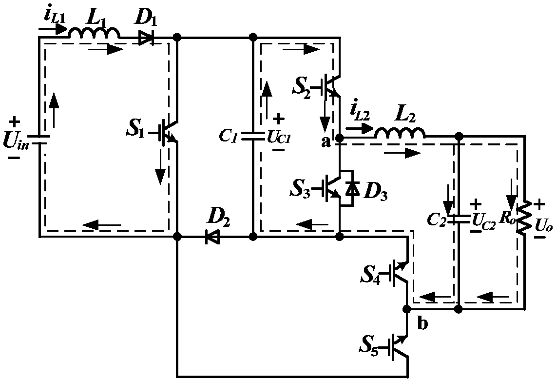
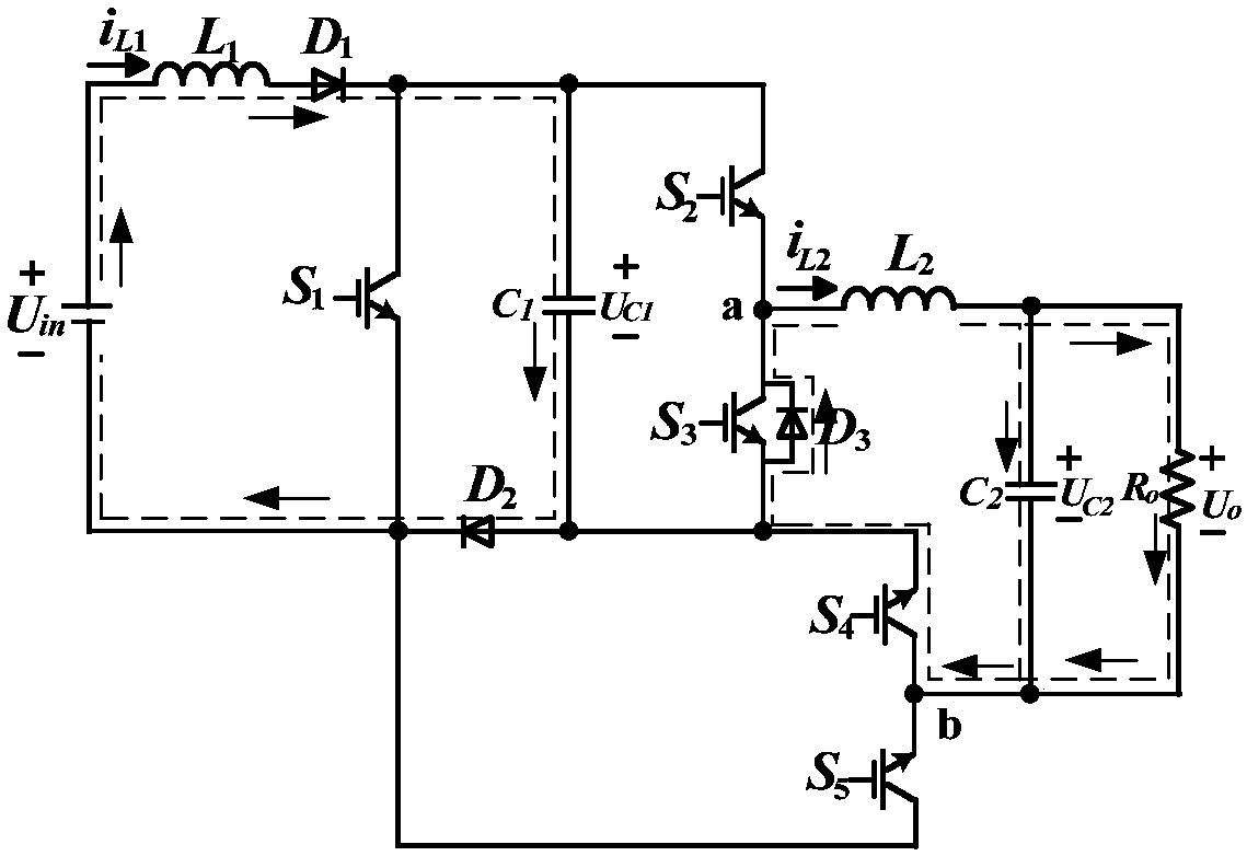
[0068] like Figure 1-7 , a single-stage boost inverter, including a power switch S 1, S 2 , S 3 , S 4 and S 5 , Diode D 1 、D 2 、D 3 , inductance L 1 and capacitance C 1 ; Inductance L 1 One end is connected to the other end of the input power supply Uin, and the inductance L 1 The other end is connected to the diode D 1 anode connected; diode D 1 The cathodes are respectively connected to the power switch tube S 1 Terminal A, power switch tube S 2 A terminal and capacitor C 1 One end; diode D 2 The anode is connected to the capacitor C 1 The other end, the power switch tube S 3 and S 4 C terminal, diode D 3 anode; diode D 2 The cathode is connected to the power switch tube S 1 The C terminal of the power switch tube S 5 A terminal and input power U in The other end; diode D 3 Cathode, power switch tube S 2 The C terminal and the power switch tube S 3 Terminal A of A is connected to node a; the power switch tube S 4 A terminal and the power switch tu...

Embodiment 2

[0071] like Figure 1-7 , a single-stage boost inverter of this embodiment, on the basis of Embodiment 1, also includes a filter, the nodes a and b are connected to the input end of the filter, and the output end of the filter is connected to the load R O connection, further, in this embodiment, the filter is LC type, including filter inductor L 2 and filter capacitor C 2 , filter inductance L 2 One end is connected to node a, and the filter inductor L 2 The other end is connected to the filter capacitor C 2 One end and grid or load R O Connected at one end, the filter capacitor C 2 The other end and the grid or load R O The other end is connected to node b.

[0072] In this embodiment, the step-up inverter is completed, and the output terminal of the filter, that is, the output voltage u o directly for the load R o power supply, or the output voltage u o Feedback to the grid.

[0073] This embodiment also includes a control method for a single-stage boost inverter...

Embodiment 3

[0124] A single-stage boost inverter in this embodiment has the same basic structure as that in Embodiment 1 or 2, and further, because the capacitor C 1 As an energy storage element, it plays the role of energy conversion, and the capacitor C 1 It is a non-polar capacitor, which makes the circuit work reliably and increases the working life of the circuit; the control method of a single-stage boost inverter in this embodiment is the same as that in Embodiment 2.


PUM


Abstract

The invention discloses a single-stage boost inverter, and belongs to the technical field of power electronic converters. The single-stage boost inverter comprises power switch tubes S1, S2, S3, S4 and S5, diodes D1, D2 and D3, an inductor L1 and a capacitor C1; one end of the inductor L1 is connected with one end of an input power supply Uin; the other end of the inductor L1 is connected with theanode of the diode D1; the cathode of the diode D1 is connected with the A end of the power switch tube S1, the A end of the power switch tube S2 and one end of the capacitor C1, respectively; the anode of the diode D2 is connected with the other end of the capacitor C1, the power switch tube S3, the C end of the power switch tube S4 and the anode of the diode D3, respectively; and the cathode ofthe diode D2 is connected with the C end of the power switch tube S1, the A end of the power switch tube S5 and the other end of the input power supply Uin, respectively. Aiming at the problem of lowstep-up ratio of the boost converter in the prior art, the single-stage boost inverter is high in integration level and relatively high in step-up ratio.

Description

technical field [0001] The invention relates to the technical field of power electronic converters, in particular to a single-stage boost inverter and a control method thereof. Background technique [0002] In the current context of increasingly tense global energy supply, the control and transformation of renewable energy distributed power generation, AC starter control, electric vehicle drive, new starter power generation technology, etc., are inseparable from power electronic inverter technology. Therefore, it is of great practical significance to develop a boost inverter technology with high efficiency, high reliability, high power density and small size. [0003] The traditional low-power inverter system is mainly realized by two stages, the DC boost circuit and the inverter circuit. The inverter circuit generally adopts a full-bridge structure, and there are many switching devices, which increases the cost of the system and the complexity of control. The space is larg...

Claims


Application Information

Patent Timeline
Patent Type & Authority Applications(China)
IPC IPC(8): H02M7/537
CPCH02M7/537
Inventor 胡雪峰张梦章家岩陈浩
Owner 合肥龙智机电科技有限公司
Why Eureka
Try Eureka