Boosting half-bridge inverter and control circuit and method thereof
A half-bridge inverter and capacitor technology, which is applied to electrical components, AC power input conversion to DC power output, output power conversion devices, etc., can solve problems such as low boost ratio
- Summary
- Abstract
- Description
- Claims
- Application Information
AI Technical Summary
Problems solved by technology
Method used
Image
Examples
Embodiment 1
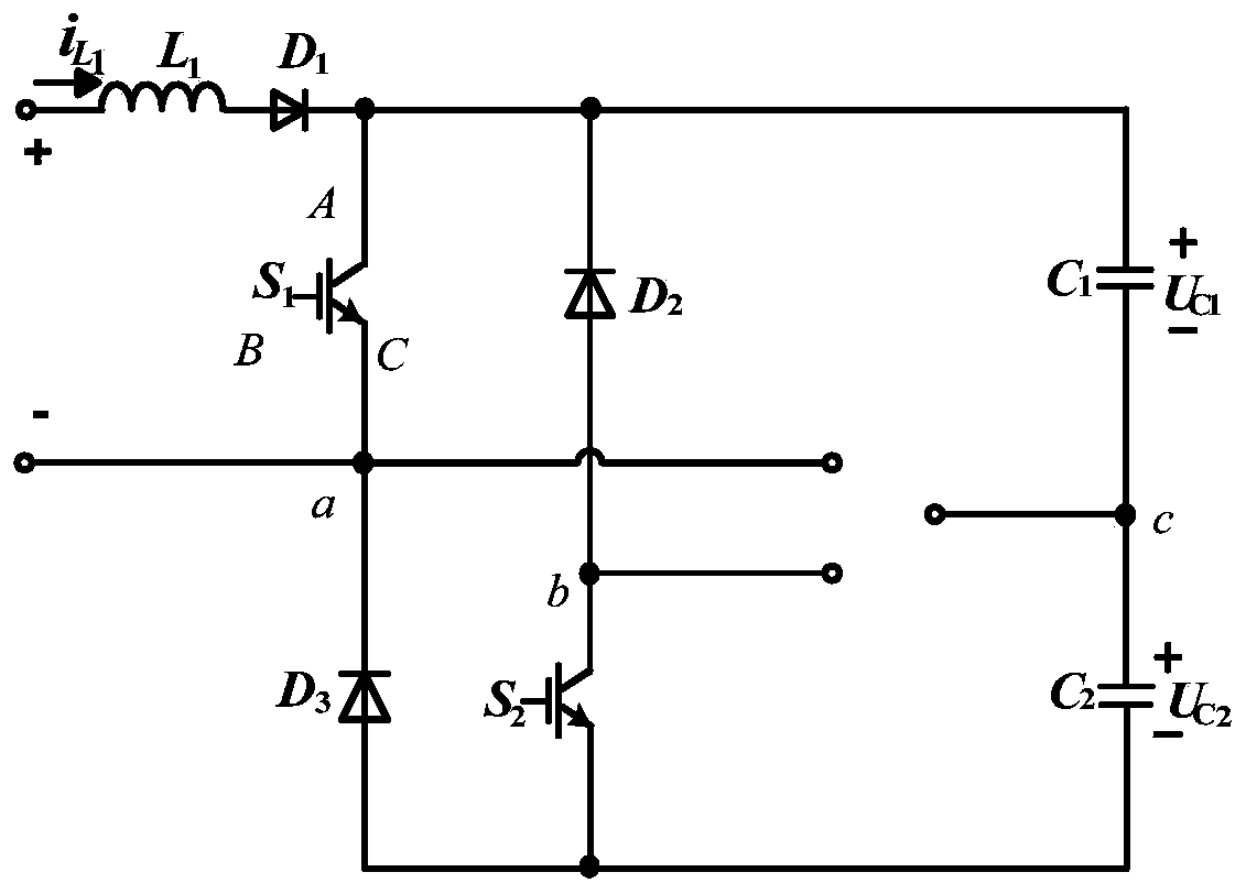
[0100] Such as figure 1 It is a schematic diagram of the circuit topology structure of the present invention. This embodiment proposes a boost half-bridge inverter, including a power switch tube S 1 , S 2 , Diode D 1 、D 2 、D 3 , inductance L 1 and capacitance C 1 、C 2 ;in,
[0101] Inductance L 1 One end is connected to one end of the input side, the inductance L 1 The other end is connected to the diode D 1 connected to the anode;
[0102] Diode D 1 The cathodes are respectively connected to the power switch tube S 1 Terminal A, diode D 2 Cathode and Capacitor C 1 one end;
[0103] Power switch tube S 1 C terminal and diode D 3 The cathode and the other end of the input side are connected to node a;
[0104] Diode D 2 Anode and power switch tube S 2 Terminal A of is connected to node b;
[0105] Capacitance C 1 The other end is connected to the capacitor C 2 One end of is connected to node c;
[0106] Diode D 3 The anodes are respectively connected to...
Embodiment 2
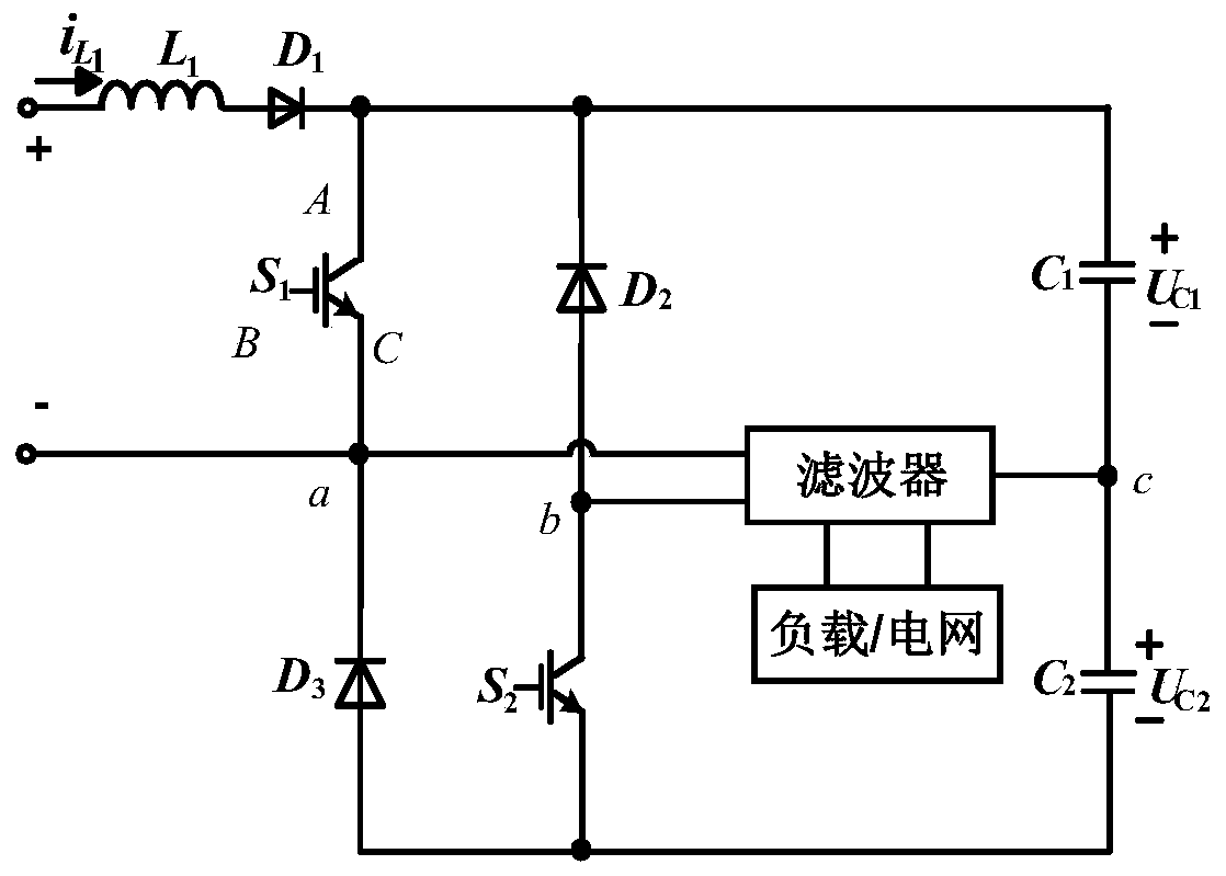
[0110] In order to further filter out harmonics or clutter on the output side, this embodiment is based on the basis of Embodiment 1, such as figure 2 for figure 1 A structural schematic diagram of a preferred mode, the output side is connected to the input side of the filter, and the output side of the filter is connected to the load or the power grid. There are various choices of filters, and three are listed here to explain clearly the content of the technical solution of the present invention.
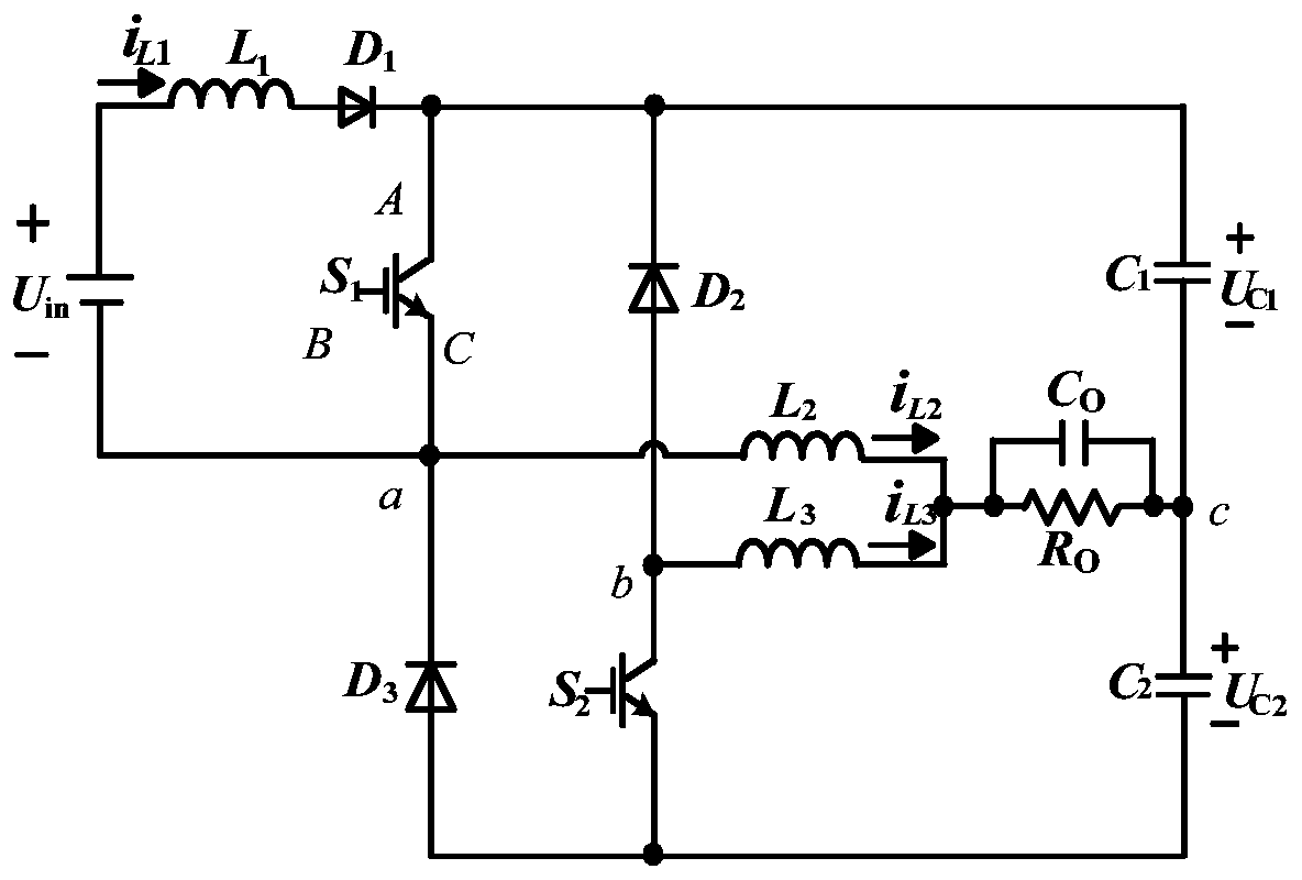
[0111] In the first case, if image 3 for figure 2 A schematic diagram of the circuit topology of the filter I used in the filter selection, the filter is a filter I, and the filter I includes a filter inductor L 2 , L 3 and filter capacitor C O , filter inductance L 2 One end is connected to node a, and the filter inductor L 2 the other end and the filter inductor L 3 One end and filter capacitor C O Connected at one end, the filter capacitor C O The other end is conne...
Embodiment 3
[0115] This embodiment relates to a control circuit of a step-up half-bridge inverter, which is applicable to a step-up half-bridge inverter in each technical solution described in Embodiments 1 and 2. Such as Figure 26 As shown, the output side voltage uo of the filter is used as the feedback voltage, and the given voltage U ref The error value is obtained by comparison, and the error value is passed through the regulator (the type of regulator can be selected according to the needs, and the attached Figure 26 The example given in is the PID regulator, which can be selected in actual use, PI, PD, etc. are not limited by the examples listed in this embodiment and the accompanying drawings) After adjustment, the triangular wave u tri Comparing to generate a pulse signal, input to the power switch tube S 1 and S 2 the B side.
PUM
 Abstract
Description
Claims
Application Information
 - R&D
- Intellectual Property
- Life Sciences
- Materials
- Tech Scout
- Unparalleled Data Quality
- Higher Quality Content
- 60% Fewer Hallucinations
Browse by: Latest US Patents, China's latest patents, Technical Efficacy Thesaurus, Application Domain, Technology Topic, Popular Technical Reports.
© 2025 PatSnap. All rights reserved.Legal|Privacy policy|Modern Slavery Act Transparency Statement|Sitemap|About US| Contact US: help@patsnap.com


