Dual-input boost inverter and control method thereof

A booster and inverter technology, applied in the field of dual-input booster inverter and its control, can solve the problems of inability to meet a wide range of needs and limited application scenarios, achieve good flexibility and reliability, overcome circuit Complex, stability-enhancing effects

Pending Publication Date: 2022-05-27
ANHUI UNIVERSITY OF TECHNOLOGY
View PDF0 Cites 0 Cited by
  • Summary
  • Abstract
  • Description
  • Claims
  • Application Information

AI Technical Summary

Problems solved by technology

The application scenarios of the above paper structure are limited and cannot meet a wide range of needs

Method used


Image

  • Dual-input boost inverter and control method thereof
  • Dual-input boost inverter and control method thereof
  • Dual-input boost inverter and control method thereof

Examples


Embodiment 1

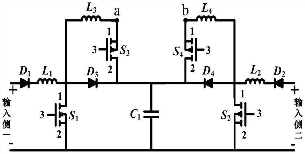
[0061] like figure 1 As shown, this embodiment proposes a dual-input boost inverter, which includes a power switch tube S 1 , S 2 , S 3 and S 4 , diode D 1 , D 2 , D 3 and D 4, the capacitance C 1 , the inductance L 1 , L 2 , L 3 and L 4 ; One end of the input side A of one of the dual-input boost inverters is connected to the diode D 1 Anode connected, diode D 1 Cathode and Inductance L 1 one end is connected, the inductor L 1 The other end of the power switch tube S 1 Terminal 1, inductance L 3 one end, diode D 3 Anode connection of D 3 The cathode and power switch tube S 3 and S 4 Terminal 2, D of 4 The cathode, capacitor C 1 The positive terminal is connected, diode D 4 The anode and the power switch tube S 2 Terminal 1, inductance L 4 one end and L 2 one end of the connection, L 2 the other end with diode D 2 The cathode is connected, the diode D 2 The anode is connected to one end of the input side 2; the other ends of the input side 1 and t...

Embodiment 2

[0064] This embodiment relates to a control circuit of a dual-input boost inverter, which is applicable to a dual-input boost inverter in each technical solution described in Embodiment 1. The inverter output side voltage is used as the feedback voltage, and the given voltage U ref Compared with the error value, the error value is passed through the regulator (the type of the regulator can be selected according to the needs, and the attached Figure 19 An example of a PID regulator is given in , which can be selected in practical application, PI, PD, etc. are not limited by this embodiment and the examples listed in the accompanying drawings) After adjustment, it is compared with a triangular wave to generate a pulse signal, which is input to the power switch Tube S 1 , S 2 , S 3 and S 4 terminal 3.

Embodiment 3

[0066] This embodiment proposes a control method for a dual-input boost inverter, which is directed to the power switch tube S 1 , S 2 , S 3 and S 4 The gate input control signal of , the waveform is as Image 6 shown, from top to bottom are the power switch tubes S 1 , S 2 , S 3 and S 4 Compared with the document "A New High-EfficiencySingle-Phase Transformerless PV Inverter Topology", there is no need to increase the dead time, and the quality of the output waveform is improved. In addition, the number of power switch tubes in the comparative literature is two more than this embodiment, which will undoubtedly increase the volume of the boost inverter, increase the switching loss, and then reduce the conversion efficiency and usage of the entire boost inverter. However, this embodiment creatively solves the above problems, and its working mode is divided into a dual power supply mode and a single power supply mode; the working modes of the dual power supply mode includ...


PUM


Abstract

The invention discloses a dual-input boost inverter and a control method thereof, and belongs to the technical field of converters. According to one scheme, one end of a first input side is connected with an anode of D1, a cathode of D1 is connected with one end of L1, the other end of L1 is connected with a terminal 1 of S1, one end of L3 and an anode of D3, a cathode of D3 is connected with terminals 2 of S3 and S4, a cathode of D4 and a positive end of C1, an anode of D4 is connected with a terminal 1 of S2, one end of L4 and one end of L2, and the other end of L2 is connected with a cathode of D2. The anode of the D2 is connected with one end of the input side II; the other ends of the input side I and the input side II, the terminals 2 of the S1 and the S2 and the negative end of the C1 are grounded; the other end of the L3 and the terminal 1 of the S3 are connected to a point a, and the other end of the L4 and the terminal 1 of the S4 are connected to a point b; nodes a and b form an output side. Double power supplies are adopted for power supply, seamless switching of the two power supplies can be achieved, normal operation of the inverter is guaranteed, the stability of the system is improved, and higher voltage gain is obtained.

Description

technical field [0001] The invention relates to the technical field of power electronic converters, in particular to a dual-input boost inverter and a control method thereof. Background technique [0002] With the gradual exhaustion of fossil energy, clean and renewable energy power generation technologies such as photovoltaics, wind energy and hydrogen energy have been highly valued worldwide. Inverter is an extremely important part in the field of new energy power generation, so the research of high-performance inverter has important practical significance. For low-voltage input renewable energy power generation systems, non-isolated boost photovoltaic inverters have the advantages of small size, low cost, and high power generation efficiency. The commonly used boost inverter circuit usually adopts a two-stage structure. If photovoltaic power generation is performed by a cascaded structure of two-stage converters, it is easy to form a barrel effect, reduce the reliability...

Claims


Application Information

Patent Timeline
Patent Type & Authority Applications(China)
IPC IPC(8): H02M7/5387H02M1/088H02J3/38
CPCH02M7/53871H02M1/088H02J3/38H02J2300/24H02J2300/28Y02E10/76
Inventor 胡雪峰穆坤书沈浩毛来安费晨进
Owner ANHUI UNIVERSITY OF TECHNOLOGY
Why Eureka
Try Eureka