A single-stage boost inverter and its control method
An inverter and single-stage technology, which is applied in the field of single-stage boost inverter and its control, can solve the problems of reducing inverter efficiency, high performance requirements of switching devices, and low DC bus voltage, etc.
- Summary
- Abstract
- Description
- Claims
- Application Information
AI Technical Summary
Problems solved by technology
Method used
Image
Examples
Embodiment 1
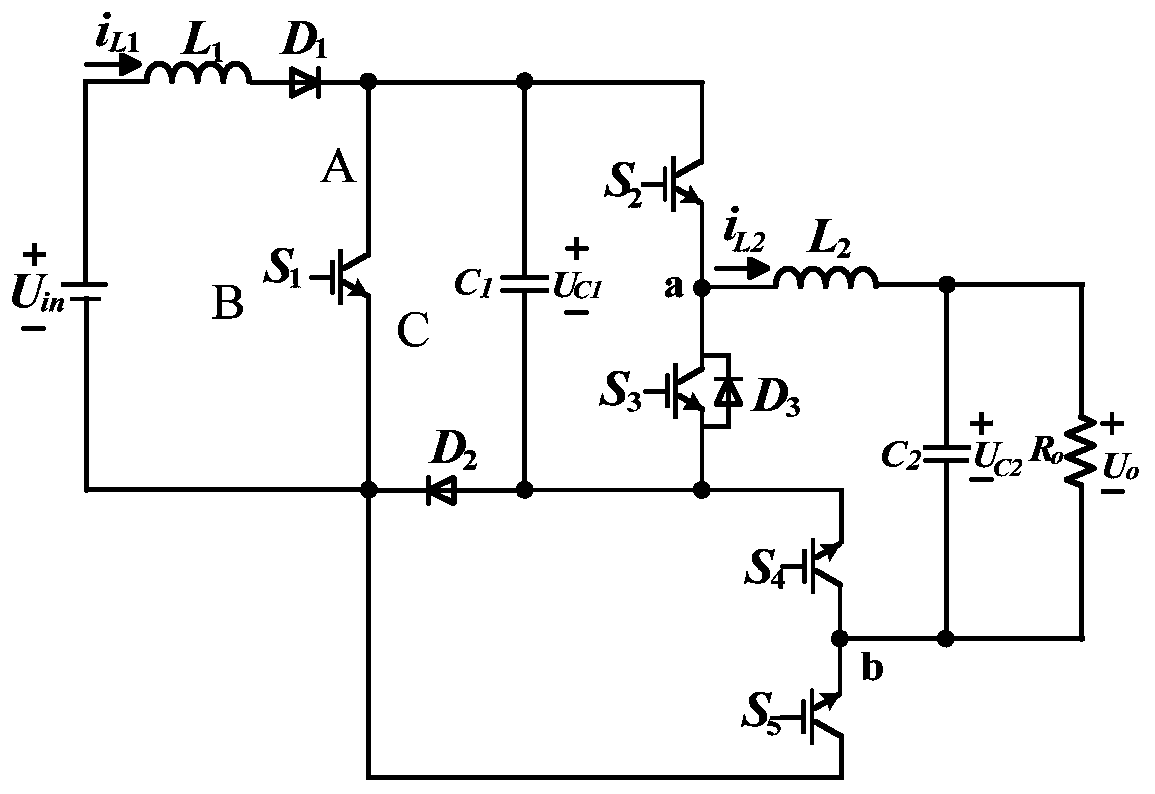
[0068] Such as Figure 1-7 , a single-stage boost inverter, including a power switch S 1, S 2 , S 3 , S 4 and S 5 , Diode D 1 、D 2 、D 3 , inductance L 1 and capacitance C 1 ; Inductance L 1 One end is connected to the other end of the input power supply Uin, and the inductance L 1 The other end is connected to the diode D 1 anode connected; diode D 1 The cathodes are respectively connected to the power switch tube S 1 Terminal A, power switch tube S 2 A terminal and capacitor C 1 One end; diode D 2 The anode is connected to the capacitor C 1 The other end, the power switch tube S 3 and S 4 C terminal, diode D 3 anode; diode D 2 The cathode is connected to the power switch tube S 1 The C terminal of the power switch tube S 5 A terminal and input power U in The other end; diode D 3 Cathode, power switch tube S 2 The C terminal and the power switch tube S 3 Terminal A of A is connected to node a; the power switch tube S 4 A terminal and the power switch...
Embodiment 2
[0071] Such as Figure 1-7 , a single-stage boost inverter of this embodiment, on the basis of Embodiment 1, also includes a filter, the nodes a and b are connected to the input end of the filter, and the output end of the filter is connected to the load R O connection, further, in this embodiment, the filter is LC type, including filter inductor L 2 and filter capacitor C 2 , filter inductance L 2 One end is connected to node a, and the filter inductor L 2 The other end is connected to the filter capacitor C 2 One end and grid or load R O Connected at one end, the filter capacitor C 2 The other end and the grid or load R O The other end is connected to node b.
[0072] In this embodiment, the step-up inverter is completed, and the output terminal of the filter, that is, the output voltage u o directly for the load R o power supply, or the output voltage u o Feedback to the grid.
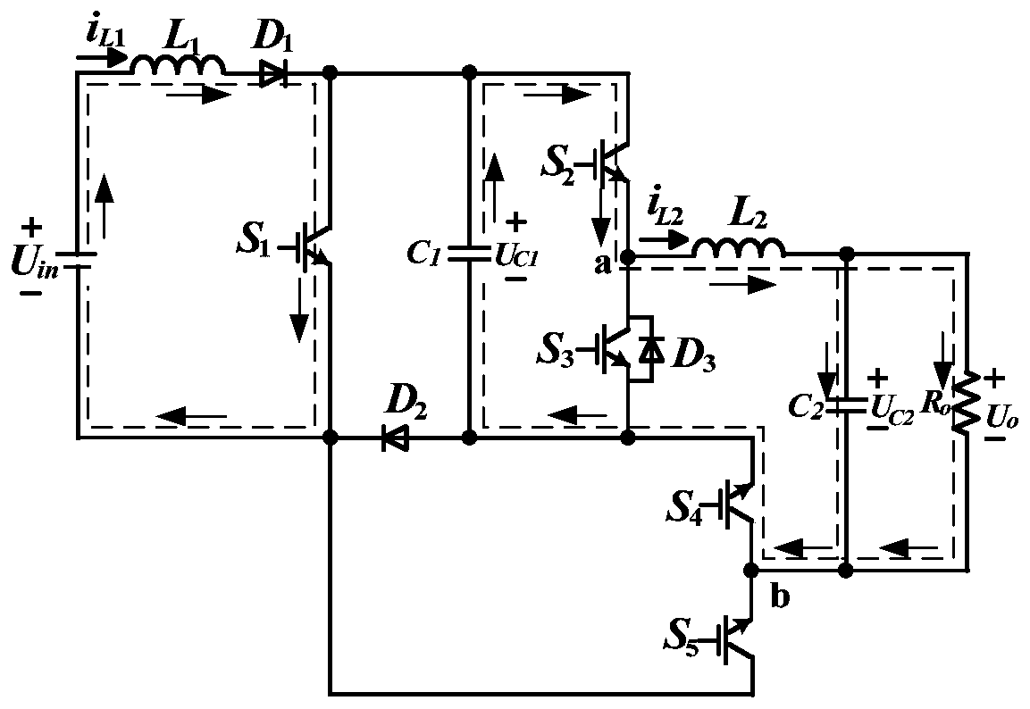
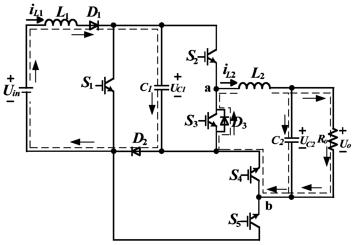
[0073] This embodiment also includes a control method for a single-stage boost inver...
Embodiment 3
[0124] A single-stage boost inverter in this embodiment has the same basic structure as that in Embodiment 1 or 2, and further, because the capacitor C 1 As an energy storage element, it plays the role of energy conversion, and the capacitor C 1 It is a non-polar capacitor, which makes the circuit work reliably and increases the working life of the circuit; the control method of a single-stage boost inverter in this embodiment is the same as that in Embodiment 2.
PUM
 Abstract
Description
Claims
Application Information
 - R&D
- Intellectual Property
- Life Sciences
- Materials
- Tech Scout
- Unparalleled Data Quality
- Higher Quality Content
- 60% Fewer Hallucinations
Browse by: Latest US Patents, China's latest patents, Technical Efficacy Thesaurus, Application Domain, Technology Topic, Popular Technical Reports.
© 2025 PatSnap. All rights reserved.Legal|Privacy policy|Modern Slavery Act Transparency Statement|Sitemap|About US| Contact US: help@patsnap.com


