Nacelle fan cowl tangential restraint

An engine nacelle and limiter technology, applied in the field of aircraft, can solve problems such as reducing efficiency and increasing the weight of aircraft

Inactive Publication Date: 2018-04-03
THE BOEING CO
View PDF0 Cites 0 Cited by
  • Summary
  • Abstract
  • Description
  • Claims
  • Application Information

AI Technical Summary

Problems solved by technology

However, such solutions increase the ...

Method used


Image

  • Nacelle fan cowl tangential restraint
  • Nacelle fan cowl tangential restraint
  • Nacelle fan cowl tangential restraint

Examples


Embodiment approach

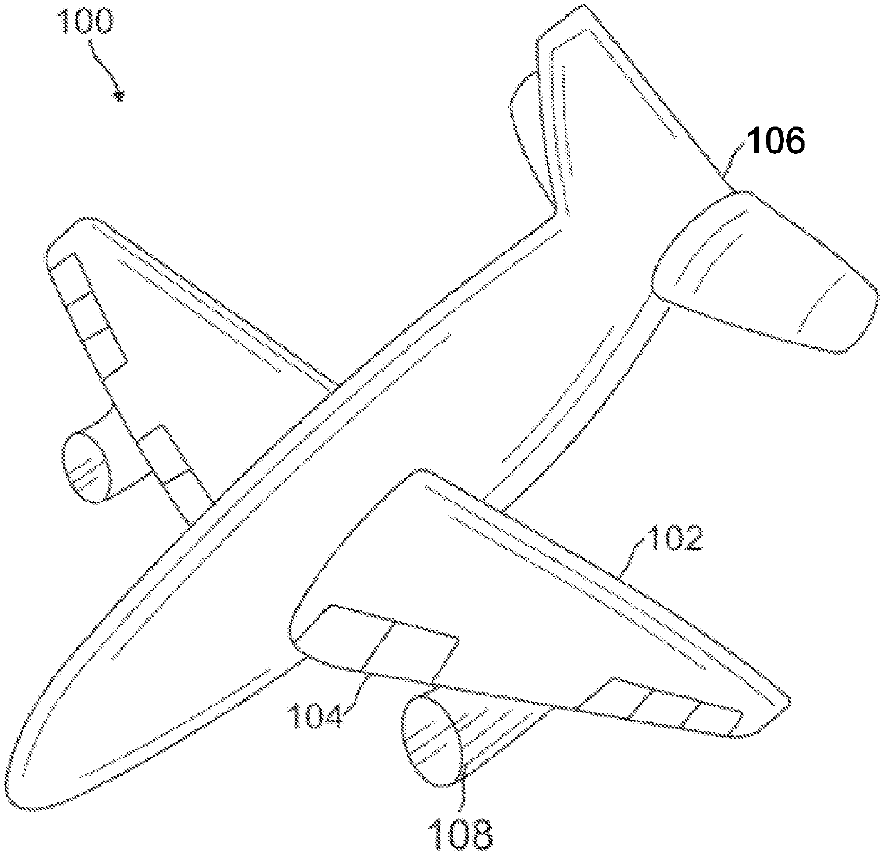
[0049] Clause 1. An aircraft propeller comprising:

[0050] core engine;

[0051] a fixed nacelle section that confines the core engine and includes the nacelle latch; and

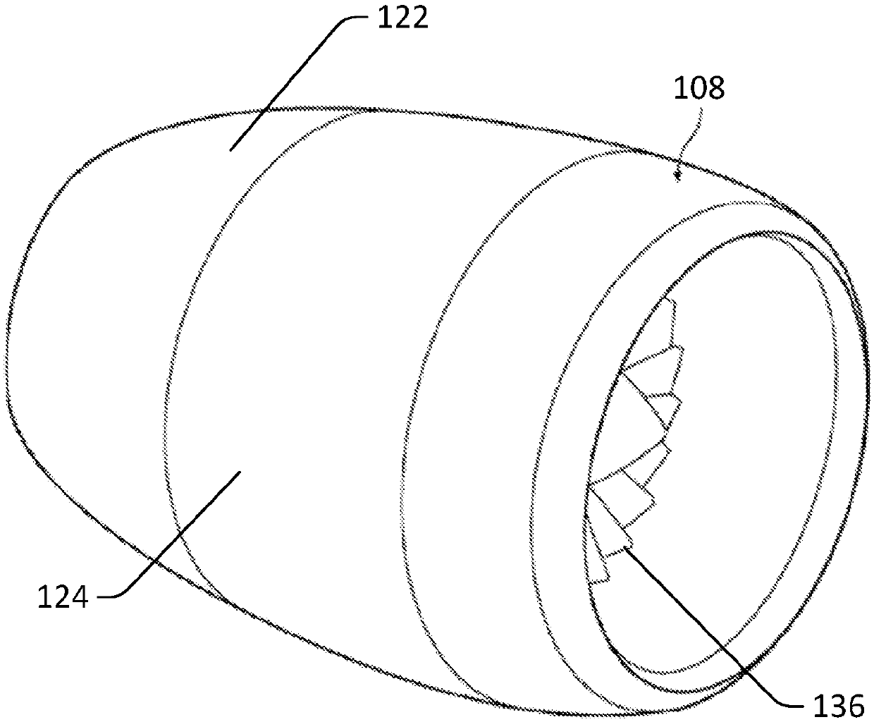
[0052] A fan cowl configured to rotate about at least a first axis and comprising:

[0053] a fan cowl latch configured to attach to the nacelle latch, and

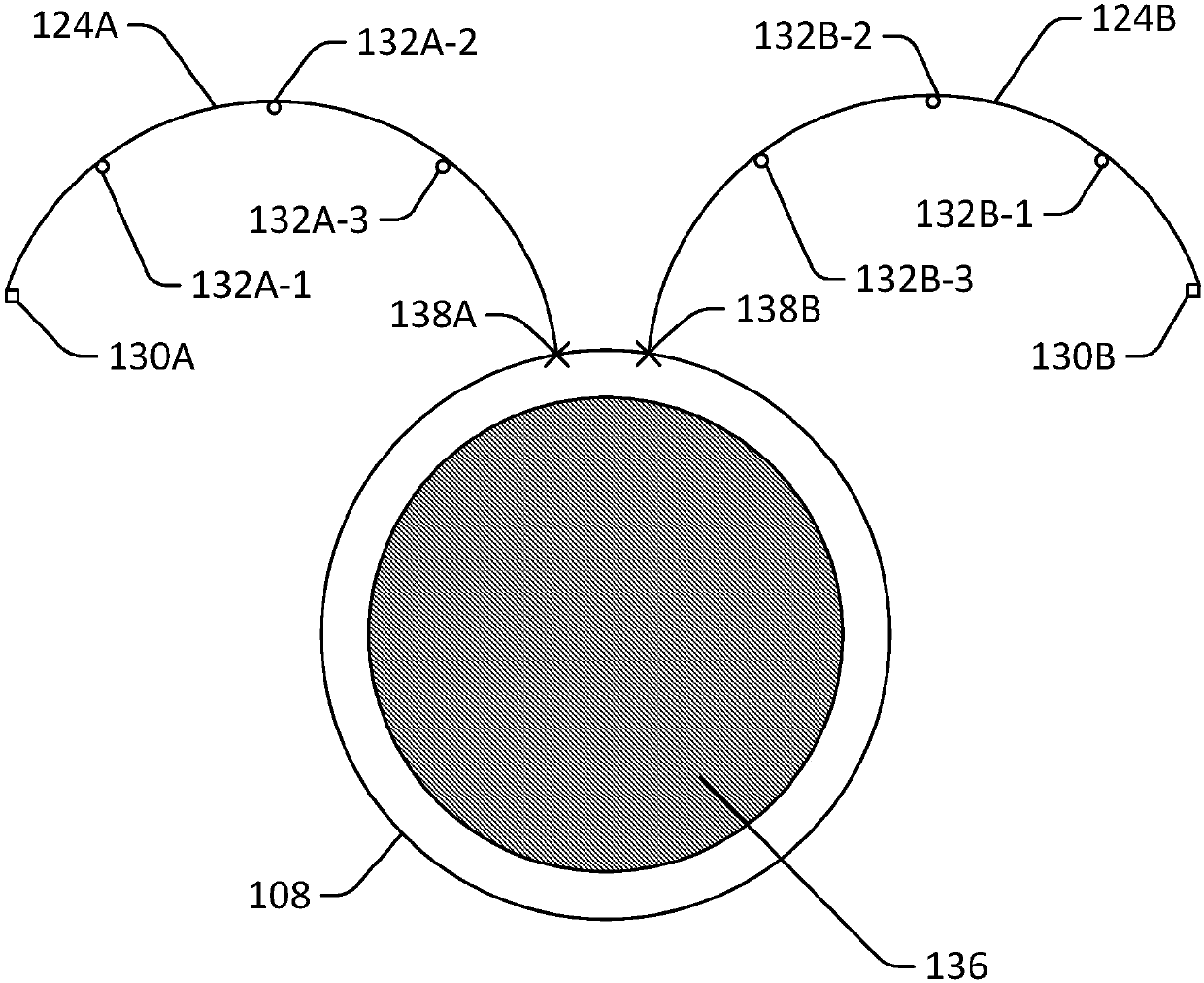
[0054] a tangential limiter configured to convert at least a portion of the radial load received by the fan cowl into membrane tension through the fixed nacelle portion of the contact portion when the fan cowl locker and the nacelle locker are coupled together .

[0055] Clause 2. The aircraft propeller of clause 1, further comprising a plurality of tangential restrictors, each tangential restrictor configured to convert at least a portion of the radial load received by the fan cowl into membrane tension.

[0056] Clause 3. The aircraft propeller of clause 2, wherein the plurality of tangential restrictors are arranged at regular intervals on the ...


PUM


Abstract

The invention is entitled nacelle fan cowl tangential restraint. Systems and methods are provided for an aircraft propulsor (108) with a fan cowl with one or more tangential restraints. The tangentialrestraints may be configured to contact one or more tangential receiving portions of a fixed portion of the aircraft propulsor (108). The fan cowl may receive a load that may include a bending load.The tangential restraints may be configured to convert the bending load to membrane tension and thus decrease deflection of the fan cowl.

Description

technical field [0001] The present disclosure relates generally to aircraft, and more particularly to aircraft propellers and aircraft propeller fan cowl structures. Background technique [0002] Aircraft fan cowls can deflect under load, which can lead to increased drag and fuel consumption. Typically, fan cowl material thickness is increased and / or additional ribbed structures are added to reduce such deflection. However, such solutions increase the weight of the aircraft and reduce efficiency. Contents of the invention [0003] Disclosed herein are systems and methods for a tangential restraint for a fan cowl to reduce deflection. In one example, aircraft propellers may be provided. The aircraft propeller may include a core engine, a fixed nacelle portion constraining the core engine and including a nacelle latch, and a fan cowl configured to rotate about at least a first axis. The fan cowl may include a fan cowl latch configured to connect to the nacelle latch and ...

Claims


Application Information

Patent Timeline
IPC IPC(8): B64D29/02B64D29/06
CPCB64D29/02B64D29/06B64D29/08
Inventor J·F·约珥
Owner THE BOEING CO
Why Eureka
Try Eureka