Magnetic-control switches

A control switch, magnetic technology, applied in the direction of magnetic/electric field switches, electrical switches, electrical components, etc., to achieve the effect of simple structure and convenient use

Inactive Publication Date: 2007-06-20
赵舜培
View PDF7 Cites 0 Cited by
  • Summary
  • Abstract
  • Description
  • Claims
  • Application Information

AI Technical Summary

Problems solved by technology

But above-mentioned these products all have certain deficiency, and its people need to be provided with touch-press type button or button on switchgear, and it does not completely change the defective of existing product

Method used


Image

  • Magnetic-control switches
  • Magnetic-control switches
  • Magnetic-control switches

Examples


Embodiment Construction

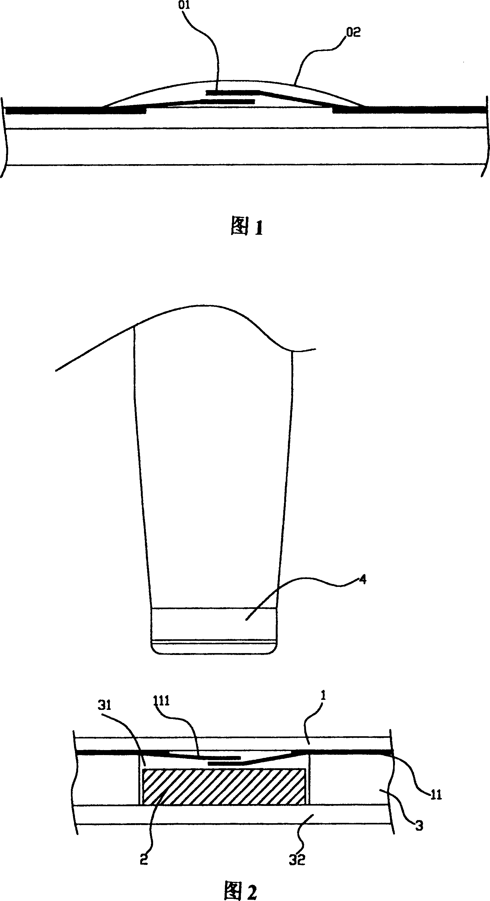
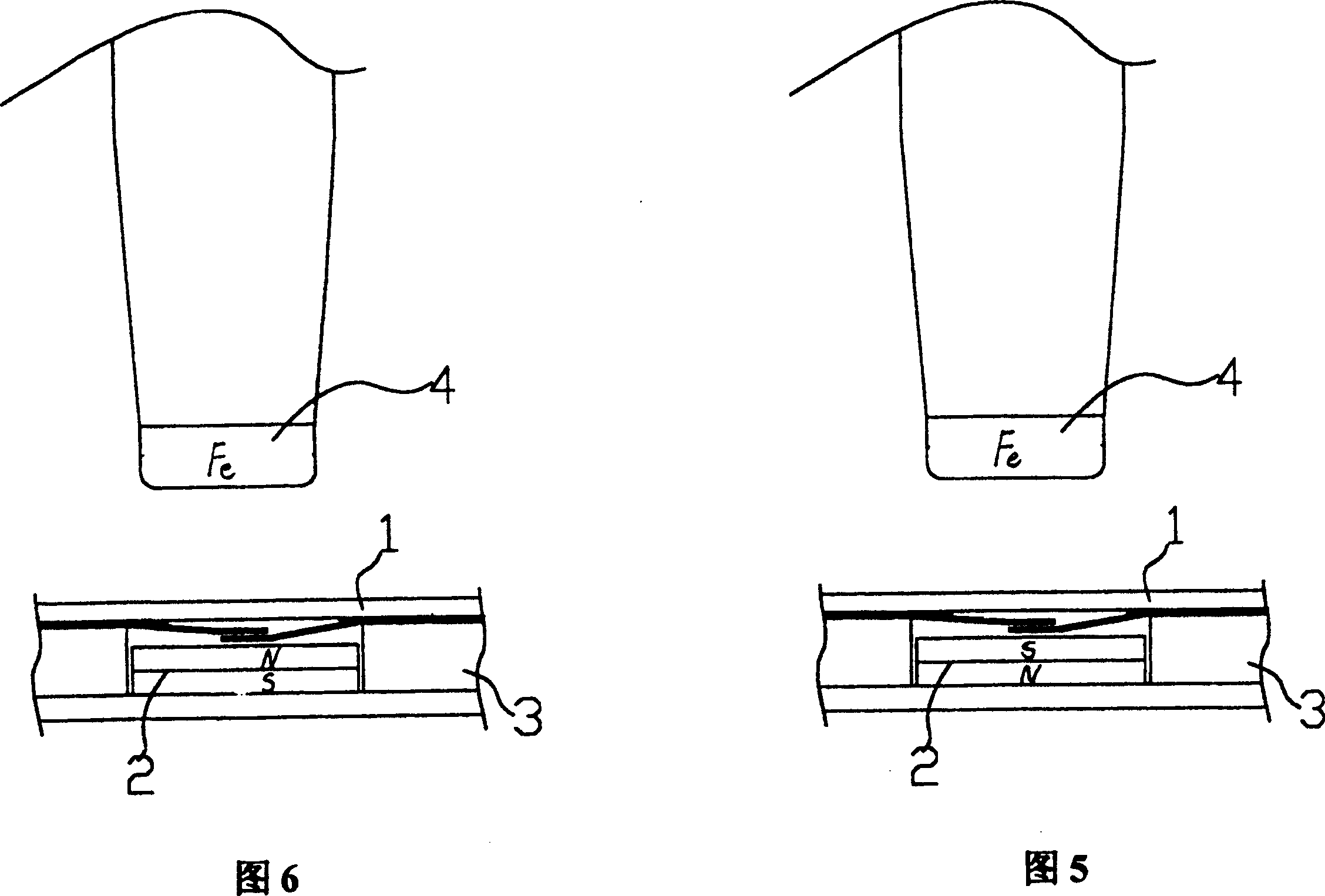
[0014] The invention mainly includes: a circuit board 1 , a pressure contact block 2 and a contact 4 made of mutually attractable materials, and a bottom plate 3 for carrying the pressure contact block 2 . The bottom plate 3 is provided with a groove 31 for placing the pressing block 2. The depth of the groove 31 should be greater than the thickness of the pressing block 2, so that the pressing block 2 will not press against the connecting contact 111 under normal conditions. The circuit board 1 is covered on the base plate 3 ; the circuit board 1 is distributed with the circuit 11 , and the connection contact 111 of the circuit 11 is located directly above the groove 31 . The circuit board 1 is usually a printed circuit board, which can greatly reduce the volume of the product because of its thin thickness. The base plate 3 is made of insulating material, and the bottom of the base plate 3 is a layer of plastic film 32 , on which the contact pressure block 2 is fixed. In thi...


PUM


Abstract

The device consists of circuit board, contact and contact block made of material which is attracted to each other as well as base to bear the contact block. The contact is moved above the contact block when the device is used. The contact block is moved up under action of magnetic force and to press against two connection contacts to switch on the line and the line is off when the contact is moved to someother place for from above the contact block because the magnetic force is disappeared and the contact block is fallen down under action self-gravity and plastic membrane tension.

Description

Technical field: [0001] The invention relates to the technical field of switch control devices, in particular to a magnetic control switch device controlled by magnetic force. Background technique: [0002] The control switch device is widely used in people's daily life. The usual control switch device is connected to the circuit by mechanical contact pressure, and the deformation of the contact pressure point in the control switch device is changed by artificial external force, so that it connects the connection contacts in the circuit. . Since this kind of switch needs to be artificially applied with external force, it is often limited in use. For example, see Figure 1, which is a touch control switch device that can be applied to various types of circuits. Touch and press the protective film 02. When in use, press the protective film 02 with your hands to make the two elastic pieces 01 contact each other, thereby connecting the circuit. After the release, the elastic pi...

Claims


Application Information

Patent Timeline
Patent Type & Authority Patents(China)
IPC IPC(8): H01H36/00
Inventor 赵舜培
Owner 赵舜培
Why Eureka
Try Eureka