power transmission device

A power transmission device and power input technology, which is applied in the direction of transmission control, toothed components, belts/chains/gears, etc., can solve the problems of increased supply costs and manufacturing costs, complex structures, etc., and achieve firm support Effect

Active Publication Date: 2019-10-18
HONDA MOTOR CO LTD
View PDF4 Cites 0 Cited by
  • Summary
  • Abstract
  • Description
  • Claims
  • Application Information

AI Technical Summary

Problems solved by technology

[0003] In Patent Document 1, as described above, although the joint state can be smoothly established between the first engaging part and the second engaging part, when relative rotation occurs, since an electric actuator is used, the The structure is complex, which also leads to higher supply costs and manufacturing costs

Method used


Image

  • power transmission device
  • power transmission device
  • power transmission device

Examples


Embodiment Construction

[0029] Hereinafter, an embodiment of the present invention will be described with reference to the drawings. Here, the up, down, front, back, and left and right sides of the vehicle body are defined based on the line of sight of the passenger riding the motorcycle.

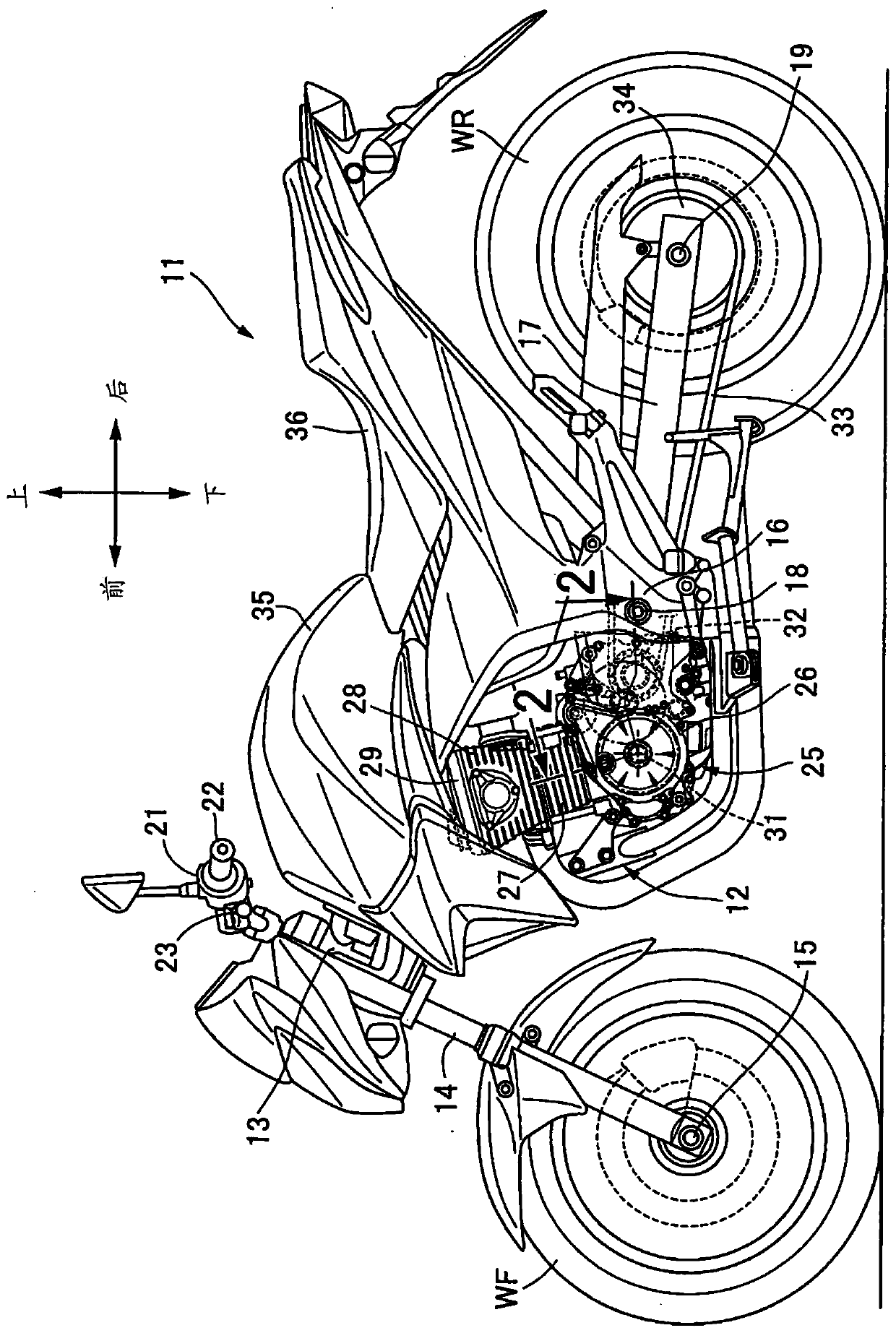
[0030] figure 1 The general structure of the motorcycle which concerns on one Embodiment of this invention is shown. The motorcycle 11 has a vehicle body frame 12 . At the front end of the vehicle body frame 12 , a front fork 14 is steerably supported by a head pipe 13 . A front wheel WF is rotatably supported on the front fork 14 around an axle 15 . At the rear end of the vehicle body frame 12 , a swing arm 17 is swingably supported by a pivot frame 16 about a support shaft 18 extending horizontally in the vehicle width direction. A rear wheel WR is rotatably supported around an axle 19 at the rear end of the swing arm 17 .

[0031] On the upper side of the head pipe 13 , a handlebar stem 21 is combined with...


PUM


Abstract

A power transmission device provided by the present invention can establish a combination state smoothly between a first fastening part of a driving gear and a second fastening part of a driven gear by a simple structure. In the power transmission device, a plurality of cam grooves (91,93) are formed on a variable speed drum (84), a sliding part (109) having an abutting surface (114) which abuts against a clutch shell (56) is in snap joint with a clutch hub (57), and an arm part (116) for driving the sliding part (109) is configured, is connected with the cam groove (93) and drives the slidingpart 109 along with the action of the variable speed drum (84), thereby enabling the sliding part 109 to abut against the clutch shell (56).

Description

technical field [0001] The present invention relates to a power transmission device, comprising: a clutch housing connected to a power input side and holding a friction plate; a clutch hub supported in a relatively rotatable manner relative to the clutch housing and holding a clutch plate capable of frictionally engaging with the friction plate The driving gear, which is connected with the clutch hub, has a first engaging portion; the driven gear, which is coaxially supported on the driving gear in an axially displaceable manner, has the ability to move from the axial reference position to the working position in the axial direction The second engaging part engaged with the first engaging part; the transmission drum, which has a cam profile that drives the driving gear in the axial direction. Background technique [0002] Patent Document 1 discloses a dog clutch type transmission. In the dog clutch type transmission, during power transmission, the first engaging portion of ...

Claims


Application Information

Patent Timeline
Patent Type & Authority Patents(China)
IPC IPC(8): F16H61/00F16H63/18F16H61/682
CPCF16H61/00F16H61/682F16H63/18
Inventor 安达惇
Owner HONDA MOTOR CO LTD
Why Eureka
Try Eureka