Method for designing curved anchor mouth

A design method, anchor lip technology, applied to anchor points, ship components, transportation and packaging, etc., can solve problems such as lightening and shortening the test period

Active Publication Date: 2018-04-06
CSSC HUANGPU WENCHONG SHIPBUILDING COMPANY
View PDF7 Cites 7 Cited by
  • Summary
  • Abstract
  • Description
  • Claims
  • Application Information

AI Technical Summary

Problems solved by technology

[0004] The purpose of the present invention is to provide a curved anchor lip design method based on the ideal anchor lip shape and shape of the anchor lip according to the shortcomings of the poor anchor state in the final link of the wooden formwork anchor pull test in the prior art. The installation angle is redesigned, so that the wooden formwork anchor test enters the final link so that the test will not fail due to poor fit of the anchorage, so that the wooden formwork anchor test items only need to focus on the smoothness of anchor lifting and anchoring to avoid It eliminates the cumbersome nuisance of the anchor test project, thereby reducing the load of the anchor test site and shortening the test cycle

Method used


Image

  • Method for designing curved anchor mouth
  • Method for designing curved anchor mouth
  • Method for designing curved anchor mouth

Examples


Embodiment 1

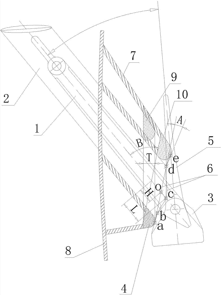
[0030] Such as Figure 1-3 As shown, this embodiment provides a method for designing a curved anchor lip, including the following steps:

[0031] 1) On the preliminary design drawing, rotate the anchorage outward to the full angle with the center of the rotating shaft as the center, suspend the anchor rod 1 in the center of the anchor chain barrel 2, and move it up and down along the center line of the anchor chain barrel 2. The auxiliary anchorage stops when the anchor crown 3 just touches the lower mouth 4 of the anchor lip, and the contact a between the anchor crown 3 and the anchor lip is obtained;

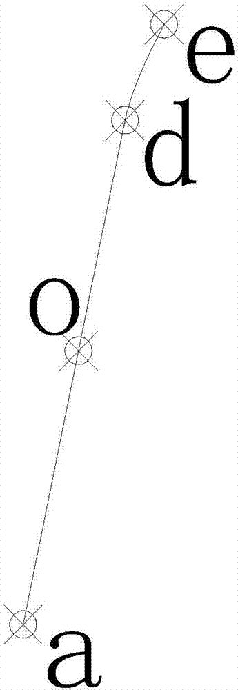
[0032] 2) Set the upper break point of the contour line of the anchor crown 3 as point b, and set the intersection point of the contour line of the anchor fluke 5 and the center line of the anchor chain barrel 2 as point c;

[0033] 3) Set the intersection point of the contour line of the anchor fluke 5 and the extension line of the inner edge of the upper opening of the anch...


PUM


Abstract

The invention relates to the field of shipbuilding tooling, in particular to a method for designing a curved anchor mouth. The method is based on an ideal anchor adhesion type to redesign the shape ofthe anchor mouth and the installation angle thereof, so that the problem that when a wooden mold cat anchor test enters a final link, the test fails due to poor anchorage device adhesion is solved, awooden mold cat anchor test project only needs to focus on the cast anchor smoothness, the disturbance of complexity of an anchor adhesion test project is avoided, a cat anchor experiment site load is alleviated, and the test cycle is shortened.

Description

technical field [0001] The invention relates to the field of shipbuilding, in particular to a method for designing a curved anchor lip. Background technique [0002] In the later stage of the anchor platform type anchor lip wooden model anchor test, the anchor is subjected to tension, the anchor rod is completely pulled into the anchor chain barrel, and the anchor claw and anchor crown are tightened and fitted on the anchor lip; when pulled to rest, The anchor is fully opened (the opening and closing angle between the anchor rod and the anchor fluke is at the maximum), the anchor rod is suspended in the middle of the chain barrel, that is, the center line of the anchor rod and the anchor chain barrel coincides, and the contact between the anchor crown and the anchor lip is at the bottom of the anchor lip. On the axis, the two contacts between the back of the two anchor flukes and the top edge of the anchor lip are on both sides of the anchor lip. If the three contacts are co...

Claims


Application Information

Patent Timeline
Patent Type & Authority Applications(China)
IPC IPC(8): B63B21/24
CPCB63B21/24
Inventor 刘元斌邹晓峰饶宇中
Owner CSSC HUANGPU WENCHONG SHIPBUILDING COMPANY
Why Eureka
Try Eureka