An adss optical cable force unloading device for an iron tower

A technology for optical cables and iron towers, which is applied in the field of ADSS optical cable force unloading devices for iron towers, can solve the problems of unsuitable middle corner towers, excessive sag of ADSS optical cables, etc., so as to prevent excessive sag, reduce the impact, and reduce the level The effect of tension

Active Publication Date: 2019-08-06
HUZHOU ELECTRIC POWER SUPPLY CO OF STATE GRID ZHEJIANG ELECTRIC POWER CO LTD +1
View PDF6 Cites 0 Cited by
  • Summary
  • Abstract
  • Description
  • Claims
  • Application Information

AI Technical Summary

Problems solved by technology

But it is not suitable for the middle corner tower, and the ADSS optical cable is prone to excessive sag after long-term use

Method used


Image

  • An adss optical cable force unloading device for an iron tower
  • An adss optical cable force unloading device for an iron tower
  • An adss optical cable force unloading device for an iron tower

Examples


Embodiment 1

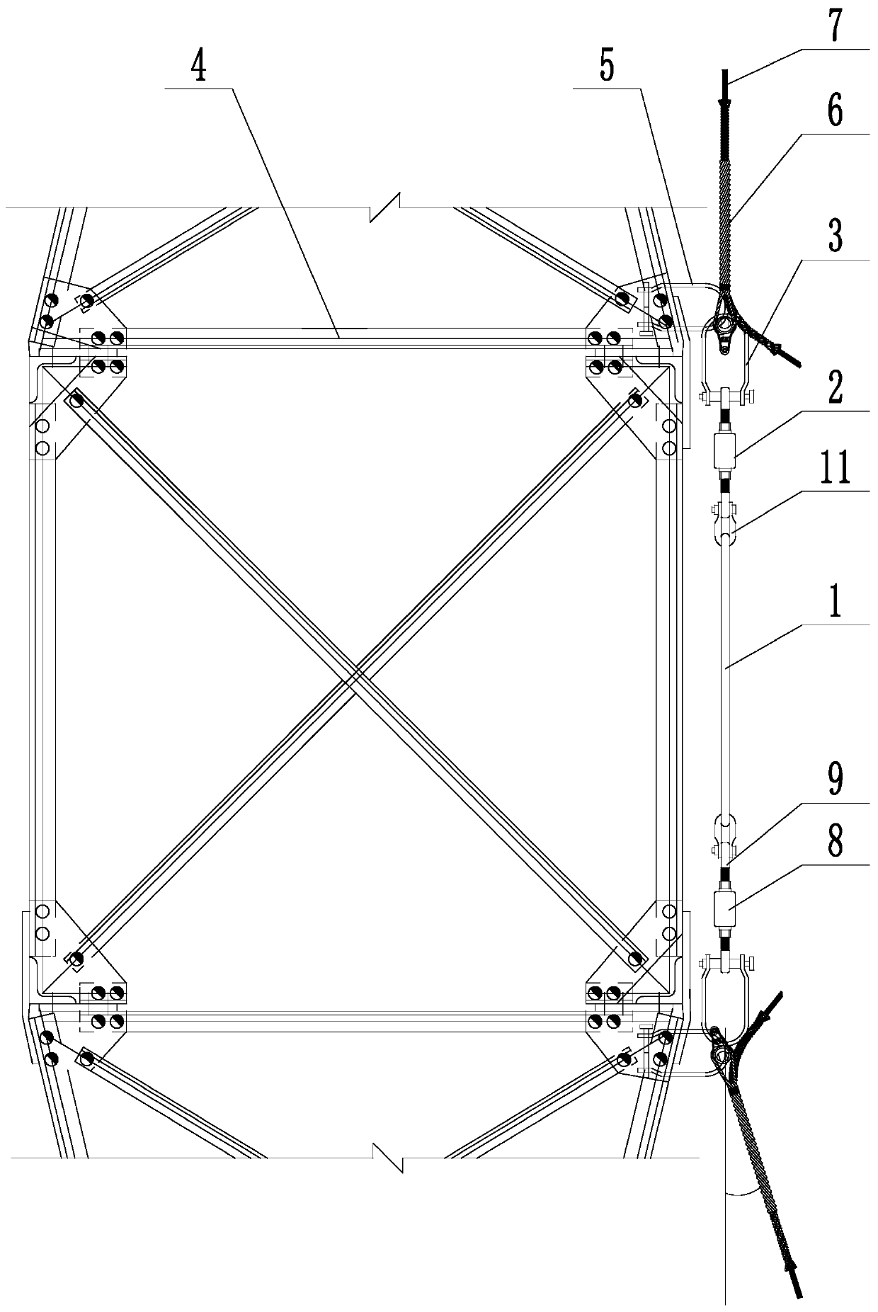
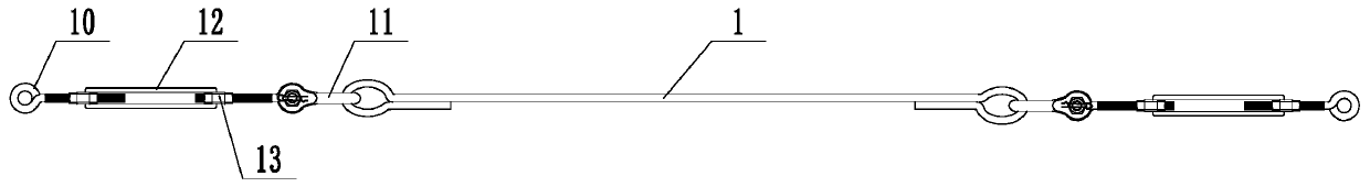
[0024] Embodiment 1: a kind of iron tower uses ADSS optical cable unloading device (referring to attached figure 1 , attached figure 2 ), including connecting rod 1, two adjusting rods 2 connected to the two ends of the connecting rod with adjustable length, and a pulling ring 3 connected to the adjusting rod. The connecting rod is a single rod, and the two pulling rings are connected for installation on the iron tower The supporting ring 5 on the 4, the pulling ring and the supporting ring are all U-shaped structures. The movable hook of the pulling ring is hung on the supporting ring, and the pulling ring is connected with a pre-twisted wire 6 for tension, and the pre-twisted wire is connected with the ADSS optical cable 7, and the two pre-twisted wires are tightened for the connecting rod. The pull ring can be adjusted and moved along the extension line direction of the connecting rod. The adjusting rod includes a rod body 8, two connecting screw rods 9 that are threaded...

Embodiment 2

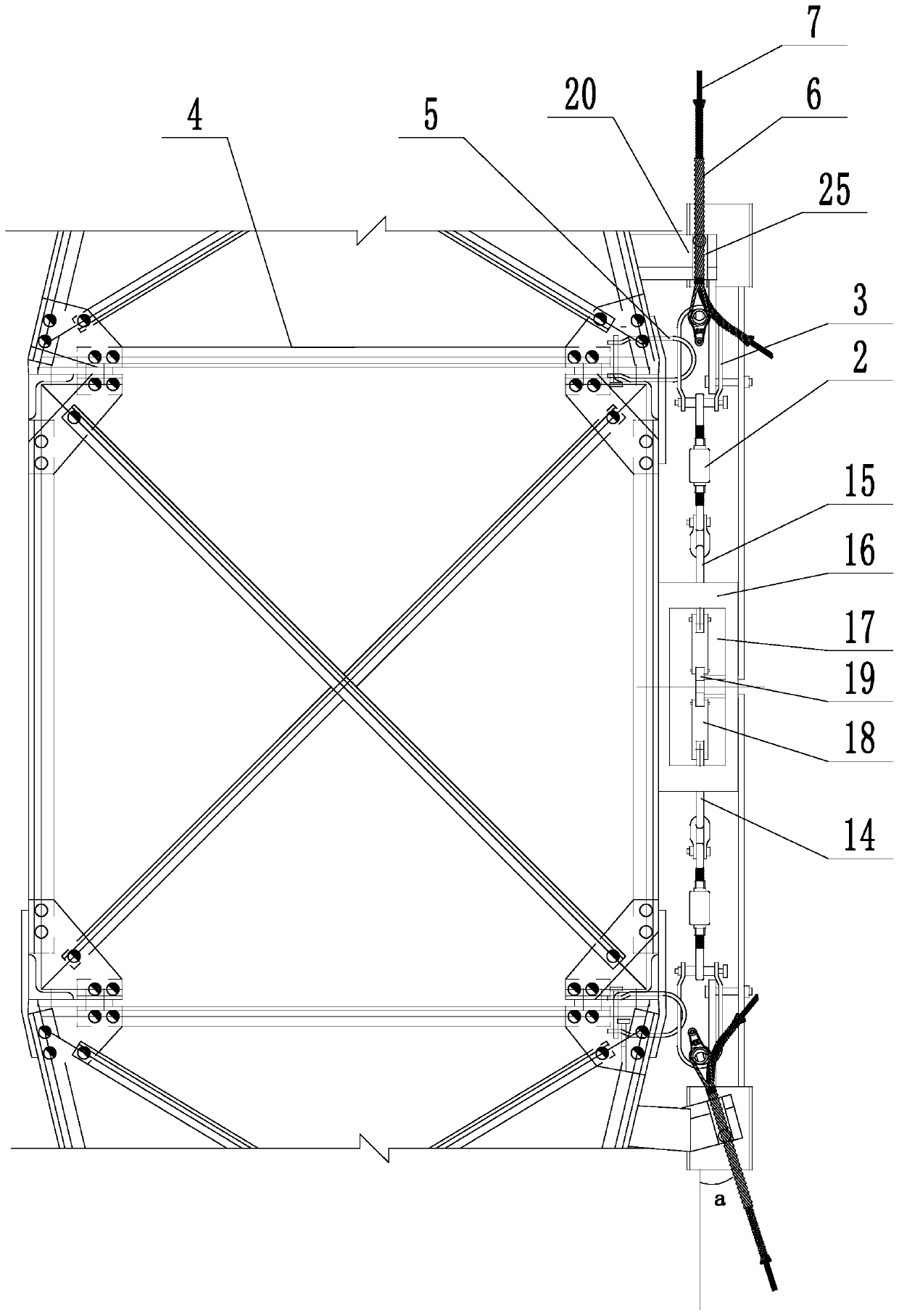
[0026] Embodiment 2: a kind of iron tower uses ADSS optical cable unloading device (referring to attached image 3 to attach Figure 5 ), its structure is similar to that of Embodiment 1, the main difference is that in this embodiment the connecting rod includes a left tie rod 14, a right tie rod 15, and a connecting support 16 between the left and right tie rods, the support is installed on the iron tower, and the support There is a slot 17 on the top, and the left and right pull rods move through the slots. The ends of the left and right pull rods are hinged to adjust the connecting rod 18, and the push block 19 is hinged between the two adjusting rods; A support block 20 is installed, and the corresponding position of the ADSS optical cable on the support block can be lifted and connected to the push column 21. The ADSS optical cable is attached to the upper end of the push column, and the lower end of the push column is abutted against the abutment plate 22. The rod is hi...


PUM


Abstract

The invention discloses an ADSS optical cable unloading device used for an iron tower, and aims at solving the defects of influencing the stability of the iron tower because of high horizontal pull force to the iron tower when the ADSS optical cable is installed on the iron tower. The ADSS optical cable unloading device comprises a connecting rod, two length-adjustable adjusting rods which are connected on the two ends of the connecting rod and pull rings which are connected on the adjusting rods. The two pull rings are connected with supporting rings which are used for being installed on theiron tower. The pull rings are flexibly hooked on the supporting rings. Pre-twisted wires are connected and tensioned on the pull rings. The pre-twisted wires are connected with the ADSS optical cables. The two pre-twisted wires tightly pull the connecting rod. The ADSS optical cables are installed on the iron tower through the unloading device so that the horizontal pull force to the iron tower can be greatly reduced, the influence on the stability of the iron tower can be reduced and the service life of the iron tower can be prolonged.

Description

technical field [0001] The invention relates to an ADSS optical cable installation auxiliary device, more specifically, it relates to an ADSS optical cable force unloading device for iron towers. Background technique [0002] At present, the ADSS optical cable is erected along with the electric power tower, and the optical cable is fixed to each level of iron tower through fittings. The iron towers at both ends and the middle corner tower use tension-resistant fittings to hold the ADSS optical cable to withstand the running tension of the optical cable. The straight line tower in the middle is suspended by hanging fittings Hang the ADSS optical cable without bearing the running tension of the optical cable. For the iron tower, the smaller the horizontal tension of the ADSS optical cable is, the better. Excessive tension will affect the stability of the iron tower. Now we can only rely on adjusting the tightness of the optical cable to reduce the tension on the iron tower by ...

Claims


Application Information

Patent Timeline
Patent Type & Authority Patents(China)
IPC IPC(8): G02B6/48
CPCG02B6/483
Inventor 臧伟吴云鹏江建军王嶔王华伟韦晓初盛建雄张力诸骏豪
Owner HUZHOU ELECTRIC POWER SUPPLY CO OF STATE GRID ZHEJIANG ELECTRIC POWER CO LTD
Why Eureka
Try Eureka