Scanning microscope

A scanning microscope and objective lens technology, applied in the field of scanning microscopes, can solve the problem of inaccurate spectral characteristics of detectors

Active Publication Date: 2018-04-17
LEICA MICROSYSTEMS CMS GMBH
View PDF5 Cites 7 Cited by
  • Summary
  • Abstract
  • Description
  • Claims
  • Application Information

AI Technical Summary

Problems solved by technology

The smaller the edge slope, the less precise the spectral characteristics of the detector

Method used


Image

  • Scanning microscope
  • Scanning microscope
  • Scanning microscope

Examples


Embodiment Construction

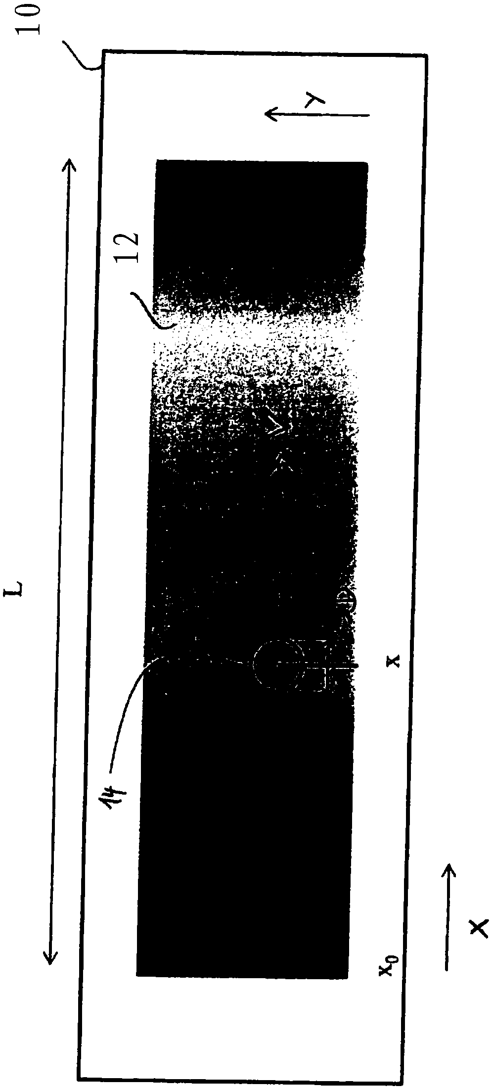
[0085] Refer below figure 1 The properties of the spectrally selective component 10, which is used according to the invention in a non-descanned detection unit for influencing the spectrum of the detection beam, will first be explained.

[0086] in accordance with figure 1 In an embodiment of the invention, the spectrally selective member 10 is a variable dichroic edge filter, such as a long-pass filter or a short-pass filter. As a long-pass filter, an edge filter transmits the spectrum above a predetermined boundary wavelength or spectral edge, while as a short-pass filter it transmits light below this predetermined boundary wavelength or spectral edge spectrum. However, it should be pointed out that the following explanations are not restricted to optical filters, but correspondingly also apply to the case where the component 10 according to the invention forms a spectrally selective beam splitter which transmits the spectrum above the spectral edge, Instead, the spectral...


PUM


Abstract

The invention relates to a scanning microscope (20) comprising: an objective (48), arranged in an illuminating beam path (26), for focusing an illuminating light bundle (24) onto a sample (52); a scanning unit (38), arranged upstream of the objective (48) in the illuminating beam path (26), for deflecting the illuminating light bundle (24) in such a way that the illuminating light bundle (24), focused via the objective (48), executes a scanning movement on the sample (52); and a detection unit (58), arranged in a detection beam path (66), for receiving the detection light bundle (54) not deflected by the scanning unit. For spectral influencing of the detection light bundle (54), the detection unit contains at least one spectrally selective component (10) which has an active surface (12) with a spectral edge which varies with the location of the incidence of the detection light bundle (54) on the active surface (12). The active surface (12) of the spectrally selective component (10) isarranged in the detection beam path (66) at the location of an image of an objective pupil (50). Alternatively, the active surface (12) is arranged in a position in which a variation of the spectral edge of the active surface, caused by a variation of the angle of incidence at which the detection light bundle strikes the active surface, said variation occurring as a result of the scanning movementof the illuminating light bundle (24), is compensated for at least partially by an opposing variation of the spectral edge of the active surface (12), which is caused by a variation of the location at which the detection light bundle (54) strikes the active surface (12).

Description

technical field [0001] The present invention relates to a scanning microscope, which comprises: an objective lens arranged in an illumination optical path for focusing an illumination beam on a sample; a scanning unit arranged upstream of the objective lens in an illumination optical path for deflecting an illumination beam, The irradiation light beam focused by the objective lens performs a scanning motion on the sample; and a detection unit arranged in the detection optical path, the detection unit is used to receive the detection light beam not deflected by the scanning unit, wherein the detection unit is configured to affect the spectrum of the detection light beam At least one spectrally selective member is included, the member has an active surface whose spectral edge varies with the incident position of the detection beam on the active surface. Such optical components are also referred to as distribution filters or variable beam splitters or variable filters. Backgrou...

Claims


Application Information

Patent Timeline
Patent Type & Authority Applications(China)
IPC IPC(8): G02B21/00G02B5/28
CPCG02B21/0076G02B5/28G02B21/0064
Inventor H·古杰尔F·诺伊加特I·波姆
Owner LEICA MICROSYSTEMS CMS GMBH
Why Eureka
Try Eureka