Inverse tone mapping based on luminance zones

A brightness and area technology, applied in image enhancement, image analysis, instruments, etc., can solve problems such as low dynamic range

Active Publication Date: 2018-04-20
INTERDIGITAL CE PATENT HLDG
View PDF5 Cites 8 Cited by
  • Summary
  • Abstract
  • Description
  • Claims
  • Application Information

AI Technical Summary

Problems solved by technology

While recent developments promise to natively capture high dynamic range content

Method used


Image

  • Inverse tone mapping based on luminance zones
  • Inverse tone mapping based on luminance zones
  • Inverse tone mapping based on luminance zones

Examples


Embodiment Construction

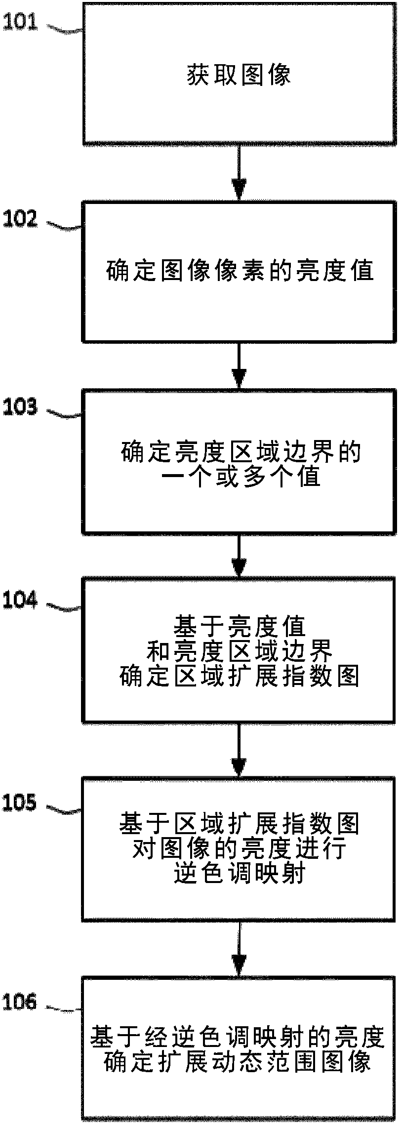
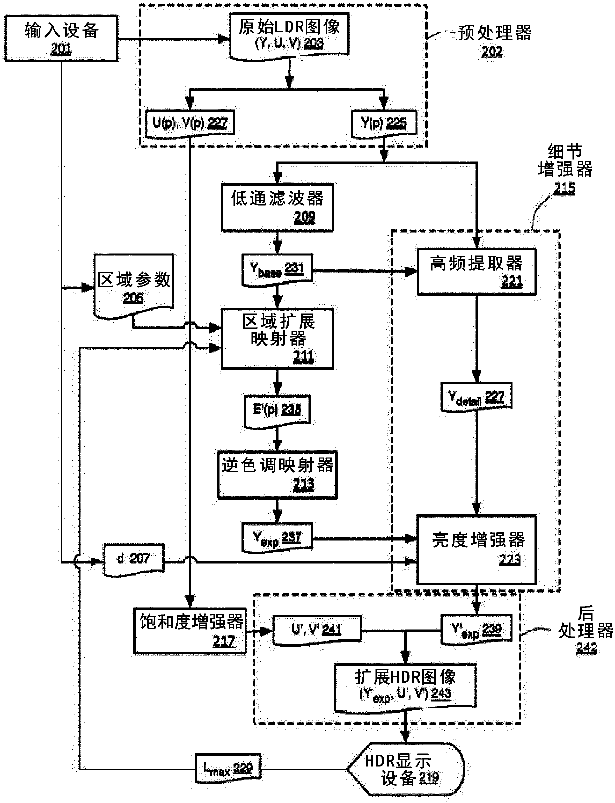
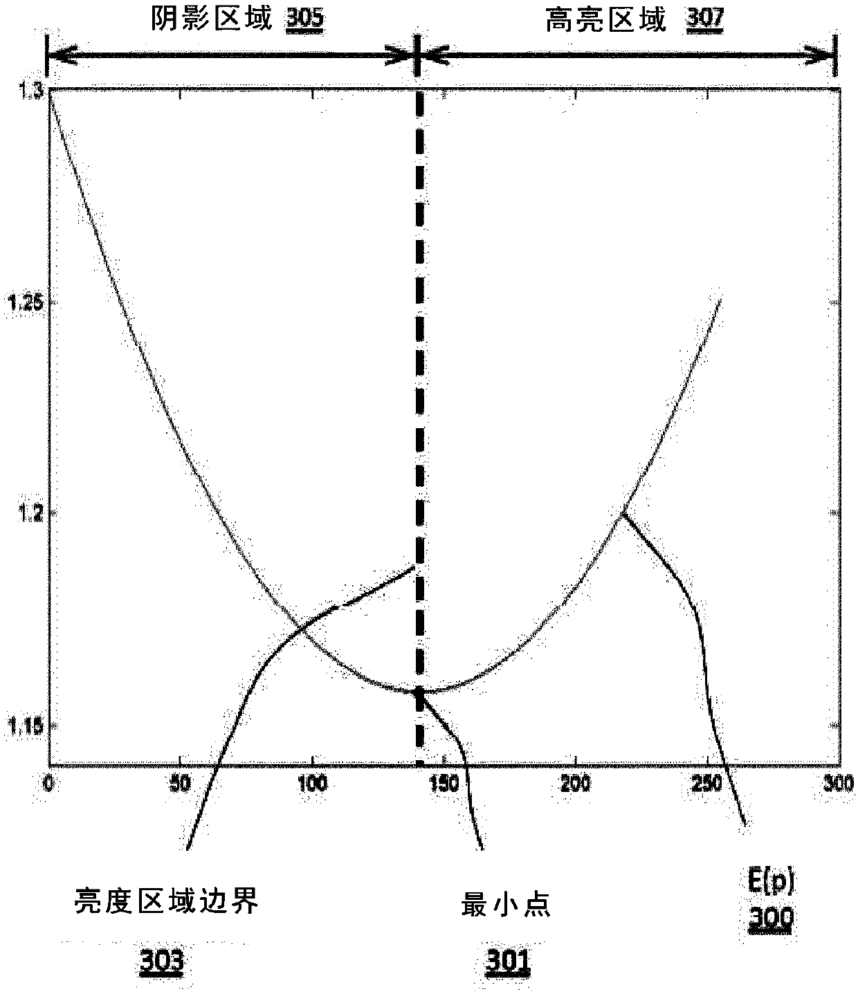
[0070] In various embodiments, a luminance region-based inverse tone mapping operator (ITMO) may be used to extend the dynamic range of content, e.g., to prepare LDR content for high dynamic range display devices, while allowing independent adjustment of different luminance regions (e.g., shadows). area, midtone area, and highlight area). For example, brightness information of colors in image content can be processed to restore or reproduce the appearance of the original scene. For example, such an ITMO can take a conventional (i.e., LDR) image as input, globally expand the brightness range of image colors, and then locally process highlights or bright regions to enhance the appearance of HDR colors in the image. However, better results can be obtained if the extension of the luminance range is adjusted to better accommodate different luminance regions.

[0071] figure 1 is a flowchart of a method of inverse tone mapping of an image based on luma regions, according to variou...


PUM


Abstract

Inverse tone mapping based on luminance zones is provided. A digital image can be obtained and luminance values of pixels of the digital image can be determined. One or more values of luminance zone boundaries can be determined. A zone expansion exponent map based on the luminance values and the one or more luminance zone boundaries can be determined. The one or more luminance zone boundaries divide the zone expansion exponent map into a plurality of luminance zones. The luminance values of the image can be inverse tone mapped based on the zone expansion exponent map. An expanded dynamic rangeimage can be provided based on the inverse tone mapped luminance values.

Description

technical field [0001] The present disclosure relates to the field of high dynamic range imaging, in particular to extending dynamic range based on brightness regions. Background technique [0002] Recent advances in display technology are beginning to allow a greater range of colors, brightness and contrast to be displayed. High Dynamic Range (HDR) technology focuses on capturing, processing and displaying content with a wider dynamic range. Despite the emergence of many high dynamic range display devices and the development of image cameras capable of capturing increased dynamic range, available high dynamic range content is still very limited. While recent developments promise to natively capture high dynamic range content in the near future, they do not address existing low dynamic range (LDR) content. Contents of the invention [0003] Inverse tone mapping based on luma regions is disclosed. A digital image can be obtained, and brightness values ​​for pixels of the...

Claims


Application Information

Patent Timeline
IPC IPC(8): G06T5/00
CPCG06T5/008G06T2207/20208G06T3/4007G06T7/90G06T5/009G06T2207/10024G06T2207/10028
Inventor 塔尼亚·波利劳伦·科万乔纳森·科威克
Owner INTERDIGITAL CE PATENT HLDG
Why Eureka
Try Eureka