Air duct device of superplastic forming hollow structure and air flow pressure differentiating method

A technology of hollow structure and superplastic forming, which is applied in the field of superplastic forming hollow structure airway devices, which can solve the problems of thinning of vertical ribs, failure of smooth expansion and rupture of airway grooves, etc.

Active Publication Date: 2018-05-04
AVIC BEIJING AERONAUTICAL MFG TECH RES INST
View PDF7 Cites 4 Cited by
  • Summary
  • Abstract
  • Description
  • Claims
  • Application Information

AI Technical Summary

Problems solved by technology

[0004] In the traditional SPF / DB three-layer structure forming, the design and control of the inflation air pressure has become a difficulty that affects the quality of the structure forming. The reason is that: in the initial stage of inflation, the air pressure is small, the airway groove cannot be expanded smoothly, and the air flow cannot enter the cavity area; as the forming air pressure rises to a certain critical value, the larger air pressure causes the groove channel to open quickly, and the relatively high-pressure inflation gas quickly enters the ribs at the front end of the solder stop, and continues to rapidly inflate each vertical rib cavity take shape
The high-pressure blowing gas deviates from the original set pressure curve and quickly enters the part, which can easily lead to three forming problems: The first forming problem is that the high-pressure gas quickly enters the cavity, which makes the forming rate of the vertical rib seriously deviate from the set optimal speed, resulting in local thinning of the stud thickness, even rupture, cavity surface wrinkles and other defects; the second forming problem is that high-pressure gas quickly enters the cavity, and due to the existence of pressure difference due to gas flow resistance, it is easy to cause defects near the airway. The forming pressure of the vertical rib in the area is high and the speed is fast, while the forming pressure of the vertical rib in the area away from the airway is low and the speed is slow, so the difference in the forming of the area is easy to cause surface wrinkles
The third forming problem is that high-pressure gas quickly enters the cavity, which is prone to inconsistent air intake rates and pressure differences on both sides of the core plate, resulting in defects such as too fast forming of the skin on one side and twisted vertical ribs

Method used


Image

  • Air duct device of superplastic forming hollow structure and air flow pressure differentiating method
  • Air duct device of superplastic forming hollow structure and air flow pressure differentiating method
  • Air duct device of superplastic forming hollow structure and air flow pressure differentiating method

Examples


Embodiment 1

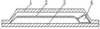
[0031] Such as Figure 1-3 As shown, a superplastic forming hollow structure airway device includes an outer plate 1 and an inner plate 3, a rib grid 2 is arranged between the outer layer plate 1 and the inner layer plate 3, and one end of the rib grid 2 is connected to a storage air cavity4.

Embodiment 2

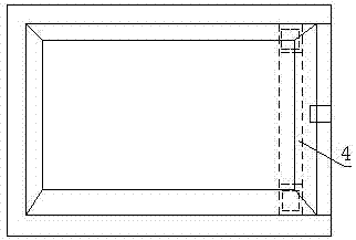
[0033] Such as Figure 1-3 As shown, a superplastic forming hollow structure airway device includes an outer plate 1 and an inner plate 3, a rib grid 2 is arranged between the outer layer plate 1 and the inner layer plate 3, and one end of the rib grid 2 is connected to a storage Air chamber 4, the side wall of the air storage chamber 4 is provided with an air flow path connected to the rib grid 2, the rib grid 2 and the air storage chamber 4 form a hollow structure, the air storage chamber 4 is located at the front end of the hollow structure, and the air storage chamber The long axis of 4 is perpendicular to the long axis of rib lattice 2.

Embodiment 3

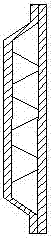
[0035] Such as Figure 1-4 As shown, a superplastic forming hollow structure airway device includes an outer plate 1 and an inner plate 3, a rib grid 2 is arranged between the outer layer plate 1 and the inner layer plate 3, and one end of the rib grid 2 is connected to a storage Air chamber 4, the side wall of the air storage chamber 4 is provided with an air flow path connected to the rib grid 2, the rib grid 2 and the air storage chamber 4 form a hollow structure, the air storage chamber 4 is located at the front end of the hollow structure, and the air storage chamber The long axis of 4 is perpendicular to the long axis of rib lattice 2.

[0036] Before the structure is formed, a core plate 8 is arranged between the outer layer plate 1 and the inner layer plate 3, a backing plate 6 is arranged between the front end of the core plate 8 and the front end of the inner layer plate 3, and the front end of the core plate 8 and the front end of the inner layer plate 3 are arrange...


PUM


Abstract

The invention relates to an air duct device of a superplastic forming hollow structure. The technical key point of the device is as follows: the device comprises an outer layer plate and an inner layer plate, wherein a rib lattice is arranged between the outer layer plate and the inner layer plate, and one end of the rib lattice is connected to a gas storage cavity. An air flow pressure differentiating method of the air duct of the superplastic forming hollow structure comprises the following steps: S1, forming the rib lattice; S2, Pre-forming the gas storage cavity in the front end of the riblattice; S3, pre-forming an air flow passageway connected to the rib lattice in the side wall of the gas storage cavity; and S4, dividing the air flow in the gas storage cavity by means of impact action of blocking a high pressure air flow to blow up the air flow, and reducing the pressure first and then blowing up second. According to the technical scheme, through the gas storage cavity, the region is expanded quickly in volume to reduce the pressure of the air flow and the air flow is stably divided into vertical rib cavities, so that the vertical rib forming process and quality are stabilized and controlled; by pre-forming the gas storage cavity to cut off the expanded air flow, quick formation of the rib lattice caused by the high pressure air flow is reduced; the blown-up gas is divided into the rib lattice cavities from the gas storage cavity, so that the air pressure differences among the vertical rib forming cavity lattices are reduced.

Description

technical field [0001] The invention relates to the technical field of superplastic forming devices and methods, in particular to a superplastic forming hollow structure airway device and an airflow partial pressure method. Background technique [0002] In the prior art, superplastic forming and diffusion bonding consist of three-layer structural blanks, such as Figure 5 shown. Solder stop flux is coated between the three slabs to form a specified internal cavity and stud structure. Among them, there is a rib grid at the front end of the solder stopper, which is used to decompose the blowing gas and guide it into the middle of each vertical rib to form small cavities, such as Figure 6 shown. [0003] In the SPF / DB three-layer structure forming process, the three slabs are combined and sealed and vacuumized to form a closed bag. First, the diffusion connection process is carried out. Outside the area, the metal layers are welded and the interface disappears; the airway g...

Claims


Application Information

Patent Timeline
IPC IPC(8): B21D26/021B21D26/059
CPCB21D26/021B21D26/059
Inventor 韩晓宁邵杰李志强
Owner AVIC BEIJING AERONAUTICAL MFG TECH RES INST
Why Eureka
Try Eureka