
Fluidized bed boiler material returning device

A technology of fluidized bed boiler and material return, which is applied in the field of thermoelectricity, can solve the problems of high cost of boiler reconstruction, achieve the effects of preventing ash accumulation, best return material effect, and optimized cross-sectional area

Pending Publication Date: 2018-05-04
YANTAI LONGYUAN POWER TECH
View PDF0 Cites 0 Cited by
  • Summary
  • Abstract
  • Description
  • Claims
  • Application Information

AI Technical Summary

Problems solved by technology

[0006] The purpose of the present invention is to provide a fluidized bed boiler return device to solve the problem of high cost of boiler reconstruction when the return standpipe does not match the boiler capacity level

Method used


Image

  • Fluidized bed boiler material returning device
  • Fluidized bed boiler material returning device
  • Fluidized bed boiler material returning device

Examples


Embodiment Construction

[0032] The technical solutions of the present invention will be further described below in conjunction with the accompanying drawings and through specific implementation methods.

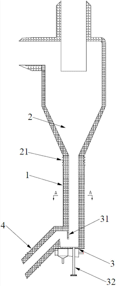
[0033] Such as figure 1 As shown, this embodiment provides a material return device for a fluidized bed boiler, including a separator 2 , a material return standpipe 1 , a material return device 3 and a material return inclined leg 4 connected in sequence. Part of the finer particles in the coal fired in the fluidized bed boiler enter the separator 2 from the outlet of the furnace (not shown in the figure), and after separation, most of the particles are separated and pass through the lower exhaust port (that is, the separator 2 bottom outlet) enters the return riser 1, and then is sent back to the furnace after passing through the return device 3 and the return inclined leg 4. Part of the extremely fine material particles fly out from the upper part of the separator 2, and enter the tail flue (not...


PUM


Abstract

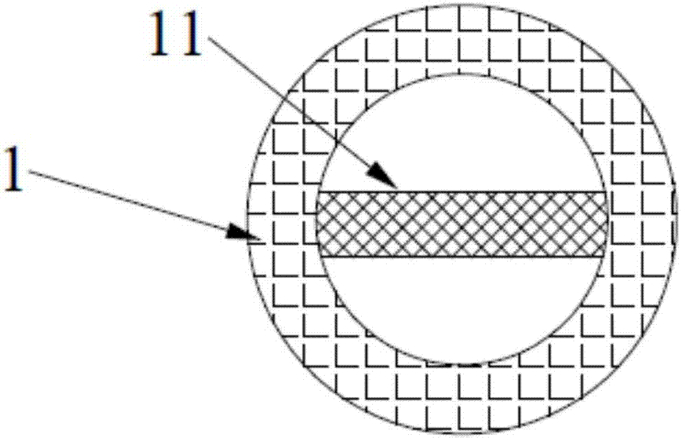
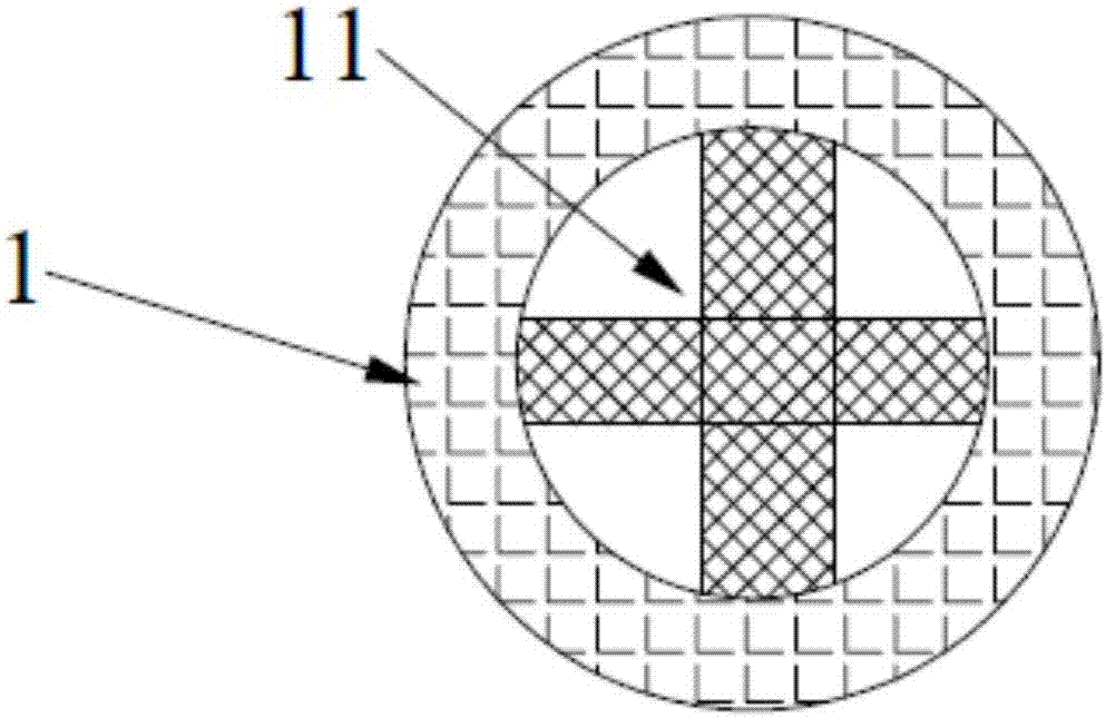
The invention discloses a fluidized bed boiler material returning device, and relates to the technical field of thermoelectricity. The fluidized bed boiler material returning device comprises a separator, a material returning vertical pipe and a material returning device which sequentially communicate with one another from top to bottom. An inner cavity of the material returning vertical pipe is provided with a cutting device capable of reducing the sectional area of the inner cavity. According to the fluidized bed boiler material returning device, the cutting device capable of reducing the sectional area of the inner cavity is arranged in the material returning vertical pipe, on the premise that the structure of the existing round material returning vertical pipe is unchanged, the sectional area of the material returning vertical pipe is optimized, thus, the optimal material returning effect is achieved, and the problem that when the material returning vertical pipe is not adaptive tothe boiler volume level, the improvement cost of a boiler is high is further solved.

Description

technical field [0001] The invention relates to the technical field of thermoelectricity, in particular to a material return device for a fluidized bed boiler. Background technique [0002] The fluidized bed boiler is composed of furnace, separator return material, tail flue and other parts. The coal enters the furnace through the coal inlet on the front and rear walls of the boiler, and is mixed with the material initially laid on the air distribution plate, and then goes through the processes of heating, ignition, rapid combustion and burnout respectively. The burnt ash moves in the furnace together with the initial material, and the larger particles are mainly deposited in the dense phase area, showing a boiling state of repeated fluidization. Part of the particles rises and flows along the furnace with the flue gas, reaches the upper part of the furnace, and then descends along the periphery of the furnace to return to the dense phase area, showing an internal circulati...

Claims


Application Information

Patent Timeline
IPC IPC(8): F23C10/26
CPCF23C10/26F23C2206/10
Inventor 王家兴王敏崔节明王冠楠路亭伟彭建升董永胜
Owner YANTAI LONGYUAN POWER TECH
Learn More