Improved water separating body with clamping device

A technology of clamping device and water dividing body, which can be used in water supply devices, indoor sanitary pipeline devices, buildings, etc., and can solve problems such as limited space

Pending Publication Date: 2018-05-08
厦门普美霖卫浴科技有限公司
View PDF0 Cites 0 Cited by
  • Summary
  • Abstract
  • Description
  • Claims
  • Application Information

AI Technical Summary

Problems solved by technology

[0002] In North America, the wall-mounted outlet pipe is often set at a height of about 2M from the ground. The problem of showering is solved by connecting a shower head (top spray) or a hand-held shower device to the outlet pipe, but it is impossible to connect an external shower head and a hand-held shower at the same time. equipment to meet the shower needs of different individuals; later the industry developed a "multifunctional tee", see patent announcement number CN2787975 for details, which added a hand-held shower on the basis of the original three-way water diversion body socket, such as figure 1 As shown, by connecting the water inlet 1a of the three-way water diversion body with the water outlet (not shown) of the water outlet pipe, the shower head and the hand-held shower head are respectively connected to the first water outlet 2a and the second water outlet of the three-way water diversion body 3a, with the help of the switch handle 4a provided on the three-way water diversion body, the water inlet 1a of the three-way water diversion body can be selectively communicated with the first water outlet 2a or the second water outlet 3a, so that the outlet pipe can be externally connected to the shower head and the shower technical solution, and because the socket 5a is additionally provided on the three-way water diversion body, it can facilitate the insertion of the handle of the hand-held shower, and also avoids the need to drill holes on the wall to set the shower wall seat or install the shower in order to install the shower. The shower rod is convenient for consumers to install; but with this scheme, since the socket 5a is arranged on the extension of the circular

Method used


Image

  • Improved water separating body with clamping device
  • Improved water separating body with clamping device
  • Improved water separating body with clamping device

Examples


no. 1 example

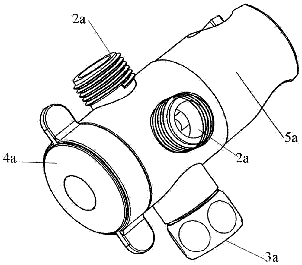
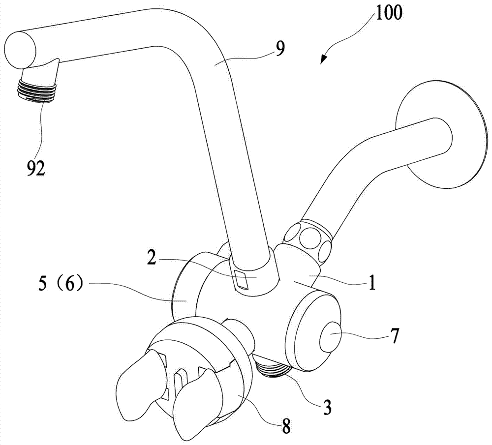
[0039] An improved water diversion body 100 with a clamping device 8, the water diversion body 100 is provided with a water inlet 1 and several water outlets, this embodiment has two water outlets, respectively the first water outlet 2 and the second water outlet The water outlet 3, the water diversion body 100 has a cylindrical body, the water inlet 1, the first water outlet 2 and the second water outlet 3 are all arranged at the radial end of the cylindrical body, and the The valve core 4 that controls the water inlet 1 to selectively connect / disconnect the first water outlet 2 and the second water outlet 3 is placed in a cylindrical body, and the actuator 5 that is externally connected to the valve core 4 is arranged on a circle. At one of the axial ends of the cylindrical body, the actuator 5 used in this implementation realizes the change of the switching angle of the valve core 4 by rotating the valve core 4 through the switching handle 6. Of course, the valve can also be...

no. 2 example

[0046] The structure of the second embodiment of the water diversion body 100 is basically the same as that of the first embodiment, except that there is a difference in the setting of the clamping device 8, specifically: it also includes a second clamping block 10 and a third spring 11; The end surface of the housing 83 is provided with a hollow portion 833, and the second clamping block 10 is flat, and the bottoms of both sides facing the left clamping arm 81 and the right clamping arm 82 are respectively provided with guiding slopes inclined from top to bottom to the outside. 101, the second clamping block 10 is placed in the hollow part 833 of the housing 83 from the inside to the outside and protrudes outward; The middle and lower part of one side of 10 forms a matching inclined surface 8114 that cooperates with the guiding inclined surface 101; the third spring 11 is located between the fixing seat 84 and the second clamping block 10; in the initial state, the left clampi...

no. 3 example

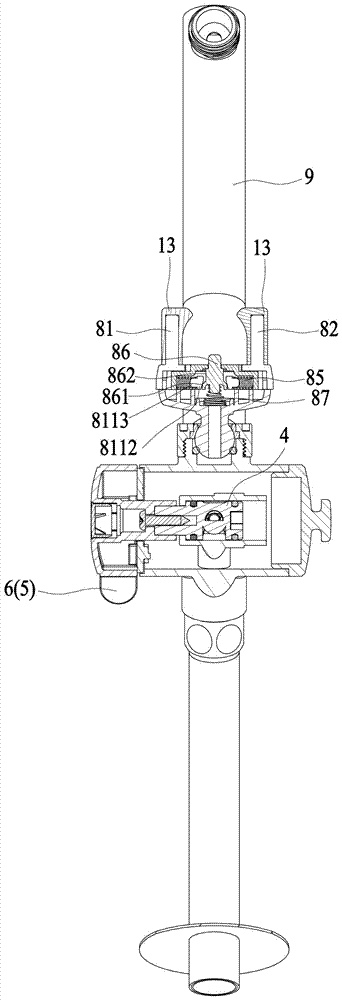
[0048] Such as Figure 10 As shown, the present invention also discloses a unilaterally movable clamping arm scheme, that is, assuming that the left clamping arm 81 is movable and the right clamping arm 82 is fixed, the end face of the shell 83 of this scheme does not need to be hollowed out, and the setting of the clamping block is cancelled. A dividing plate 834 is added in the inner side of the shell 83; a gap 831 is also required on the movable side of the housing, and a spacer 832 with a hollow cavity is provided at the gap 831; the longitudinal section of the left clamp arm 81 is L-shaped, and There is a connecting seat 811 at the bottom, and the connecting seat 811 is surrounded by two side plates 8111 and a front baffle plate 8112 to form a cavity A. Slide in as a guide positioning surface, and put the limit block 832 in its cavity A, one end of the first spring 85 is against the inner wall of the front baffle plate 8112 of the left clamp arm 81, and the other end is a...


PUM


Abstract

The invention relates to an improved water separating body with a clamping device. The water separating body is provided with a water inlet and a plurality of water outlets; a valve core for controlling the water inlet to be selectively connected or disconnected with the water outlets is arranged in the water separating body; the valve core is externally connected with an actuating piece for controlling switching of the valve core; the clamping device for automatically stretching out and drawing back according to the width of a clamping object to adjust the clamping gap is arranged on the water separating body; one water outlet connected with a shower head is connected with a bending arm for increasing the showering height; an inner cavity of the bending arm is provided with an overflowingchannel, and the top of the bending arm is provided with a water outlet; and through the arrangement, the clamping device on the water separating body is movably arranged, the gap can be automatically adjusted according to the width of the clamping object, and the application range is wider; and moreover, due to the bending arm, the showering height is increased and the showering requirement of tall people can be met well.

Description

technical field [0001] The invention relates to a clamping device for a hand-held shower, in particular, the clamping device is arranged on a water diversion body connected with a wall-embedded water outlet pipe. Background technique [0002] In North America, the wall-mounted outlet pipe is often set at a height of about 2M from the ground. The problem of showering is solved by connecting a shower head (top spray) or a hand-held shower device to the outlet pipe, but it is impossible to connect an external shower head and a hand-held shower at the same time. equipment to meet the shower needs of different individuals; later the industry developed a "multifunctional tee", see patent announcement number CN2787975 for details, which added a hand-held shower on the basis of the original three-way water diversion body socket, such as figure 1 As shown, by connecting the water inlet 1a of the three-way water diversion body with the water outlet (not shown) of the water outlet p...

Claims


Application Information

Patent Timeline
IPC IPC(8): E03C1/02E03C1/06
CPCE03C1/021E03C1/06
Inventor 余琴郭靖陈祥桂
Owner 厦门普美霖卫浴科技有限公司
Why Eureka
Try Eureka