A radiator mounting structure
What is Al technical title?
Al technical title is built by PatSnap Al team. It summarizes the technical point description of the patent document.
A technology for mounting structures and radiators, which is applied to heat exchanger shells, heat exchange equipment, lighting and heating equipment, etc., and can solve problems such as low radiator maintenance efficiency, inability to quickly inspect radiators, and poor fixing effects , to achieve the effect of quick maintenance
Active Publication Date: 2019-08-13
中山市帅扬电子科技有限公司
View PDF4 Cites 0 Cited by
Summary
Abstract
Description
Claims
Application Information
AI Technical Summary
This helps you quickly interpret patents by identifying the three key elements:
Problems solved by technology
Method used
Benefits of technology
Problems solved by technology
[0002] The radiator installation structure in the prior art cannot realize fast fixing of the radiator, the radiator fixing structure is complicated, and the fixing effect is not good; the radiator installation structure in the prior art cannot quickly check the radiator, and the maintenance efficiency of the radiator is low, so There is an urgent need for a radiator installation structure to solve the above-mentioned problems
Method used
Image
Click on the blue label to locate the original text in one second.
Reading with bidirectional positioning of images and text.
Examples
Embodiment Construction
[0020] In order to make the technical means, creative features, goals and effects achieved by the present invention easy to understand, the present invention will be further described below in conjunction with specific embodiments.
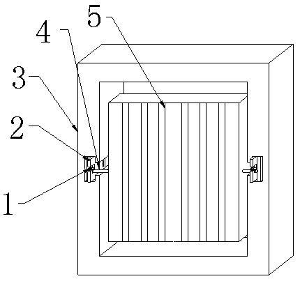
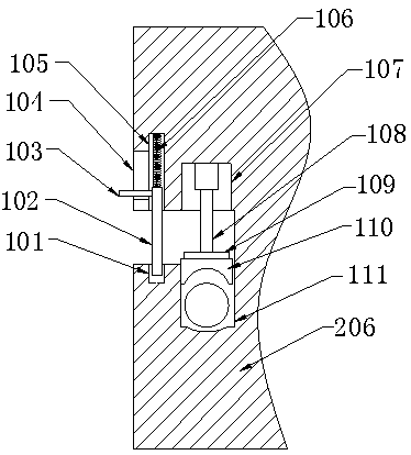
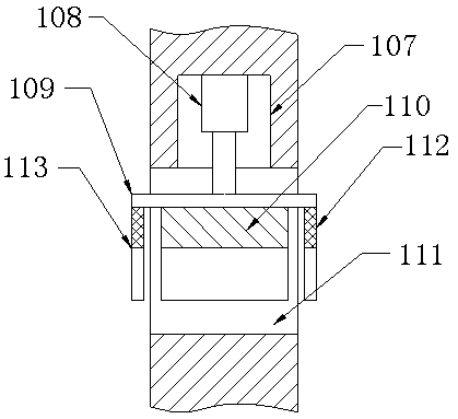
[0021] see Figure 1-Figure 5 , the present invention provides a technical solution: a radiator installation structure, including an outer frame 3, a connecting rod 4, a radiator body 5, a quick installation mechanism 1 and an inspection mechanism 2, and the connecting rod 4 is arranged on the left end surface of the radiator body 5 above, and the connecting rod 4 is connected with the outer frame 3 through the quick installation mechanism 1. The quick installation mechanism 1 includes a socket 101, a positioning rod 102, a push handle 103, a moving groove 104, a receiving groove 105, a spring 106, a groove 107, Electric push rod 108, support plate 109, clamping block 110, clamping groove 111, right clamping plate 112 and left clamping plate 113, ...
PUM
Abstract
The invention provides a radiator mounting structure. The radiator mounting structure comprises an outer framework, a connecting rod, a radiator body, a rapid mounting mechanism and an inspection mechanism; the connecting rod is arranged on the left end surface of the radiator body and connected with the outer framework by the rapid mounting mechanism; the rapid mounting mechanism comprises a plughole, a positioning rod, a pushing handle, a moving groove, a containing groove, a spring, a groove, an electric pushing rod, a supporting plate, a clamping block, a clamping groove, a right clampingplate and a left clamping plate; the inspection mechanism is arranged in the middle of the left end surface of the inside of the outer framework and the inspection mechanism comprises a first rotary shaft, a first T-shaped groove, a first guiding plate, a first limiting groove, a first limiting sliding block, a first adjusting plate, a second limiting groove, a second limiting sliding block, a second T-shaped groove, a second guiding plate, a second rotary shaft and a second adjusting plate. Compared with the prior art, the structure has the following beneficial effects of realizing the rapidfixing function of the radiator body and realizing the rapid inspection function of the radiator body.
Description
technical field [0001] The invention relates to a heat sink installation structure, which belongs to the field of heat sink technical equipment. Background technique [0002] The radiator installation structure in the prior art cannot realize fast fixing of the radiator, the radiator fixing structure is complicated, and the fixing effect is not good; the radiator installation structure in the prior art cannot quickly check the radiator, and the maintenance efficiency of the radiator is low, so There is an urgent need for a radiator installation structure to solve the above-mentioned problems. Contents of the invention [0003] In view of the deficiencies in the prior art, the purpose of the present invention is to provide a heat sink installation structure to solve the problems raised in the background art above. [0004] In order to achieve the above object, the present invention is achieved through the following technical solutions: a radiator installation structure, in...
Claims
Application Information
Patent Timeline
Application Date:The date an application was filed.
Publication Date:The date a patent or application was officially published.
First Publication Date:The earliest publication date of a patent with the same application number.
Issue Date:Publication date of the patent grant document.
PCT Entry Date:The Entry date of PCT National Phase.
Estimated Expiry Date:The statutory expiry date of a patent right according to the Patent Law, and it is the longest term of protection that the patent right can achieve without the termination of the patent right due to other reasons(Term extension factor has been taken into account ).
Invalid Date:Actual expiry date is based on effective date or publication date of legal transaction data of invalid patent.