Camera distance measuring method and system

A technology of distance measurement system and distance measurement method, which is applied in the field of camera distance measurement method and system, and can solve problems such as inaccurate estimation of optical parameters, large influence of measurement attitude, and different measurement values

Active Publication Date: 2018-05-08
珠海亿智电子科技有限公司
View PDF4 Cites 10 Cited by
  • Summary
  • Abstract
  • Description
  • Claims
  • Application Information

AI Technical Summary

Problems solved by technology

[0005] In order to solve the problems of inaccurate estimation of optical parameters in the current monocular camera distance measurement, and the measurement results are greatly affected by the measurement attitude, the present invention proposes a camera distance measurement method and system, which is different from other monocular camera distance measurement methods. The system does not need to accurately know the specific parameters of the camera lens. It only needs to obtain three sets of codeword values ​​(input parameters of the lens driver unit) under different attitudes (horizontal, overlooking and looking up) by means of calibration. When the focus is successful, the actual distance to the target object can be calculated by combining the lens driver codeword value and the pitch angle measured by the gyroscope; at the same time, this method introduces the gyroscope unit, and solves the problem by introducing the calculation of the pitch angle. Different attitudes during measurement lead to different measurement values, making the results more accurate

Method used


Image

  • Camera distance measuring method and system
  • Camera distance measuring method and system
  • Camera distance measuring method and system

Examples


Embodiment Construction

[0018] The present invention will be further described below in conjunction with the accompanying drawings.

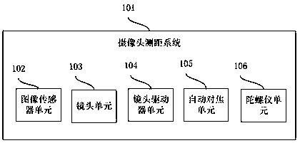
[0019] figure 1 A specific embodiment of a camera ranging system according to the present invention is shown. The camera ranging system 101 mainly includes: an image sensor unit 102, a lens unit 103, a lens driver unit 104, an autofocus unit 105, and a gyroscope unit 106 .

[0020] The image sensor unit 102, in a specific embodiment, mainly refers to a CCD or a CMOS photosensitive device, which is a device that can convert light signals into electrical signals. In a specific embodiment, the lens unit 103 mainly refers to an optical device located in front of the image sensor for gathering light to generate an image. The lens driver unit 104, in a specific embodiment, mainly includes a motor drive circuit and a lens motor. The motor drive circuit refers to a circuit device that can control the current of the lens motor. Generally, by controlling the code word value of...


PUM


Abstract

The invention discloses a camera distance measuring method and system. The system comprises an image sensor unit, a lens unit, a lens driving device unit, an automatic focusing unit and a gyroscope unit. The method mainly comprises the following steps: 1, calibrating a codon value-object distance table, namely, calibrating the codon value (input parameter of the lens driving device unit)-object distance table under three groups of different postures (horizontal posture, overlook posture and elevation posture) as requirement; 2, automatically focusing a target object to obtain the codon value of the current lens driving device unit; 3, acquiring the overlook angle and the elevation angle measured by the gyroscope unit; and 4, calculating the actual distance to the target object based on thecodon value, the overlook angle and the elevation angle of the lens driving device unit. The method and the system can be compatible to various smart devices, such as a smart phone, a laptop and thelike; in addition, the gyroscope unit is introduced, so that the problem that different measuring postures lead to different measuring values can be solved, as a result, the result accuracy is improved.

Description

technical field [0001] The invention relates to the field of electronic information systems, in particular to a camera distance measuring method and system. Background technique [0002] Judging the distance between the current position and the target object is a requirement that is often encountered in daily life. Common handheld ranging devices are generally equipped with a signal transmitting device and a receiving device, which measure the interval between the signal transmitting time and the reflected signal receiving time. Estimate the distance between it and the target object. The common signals are ultrasonic, infrared, laser, etc. At present, this kind of handheld device is generally used in professional fields, and its cost is high, so it is difficult to promote it in daily life. [0003] With the popularization of smart devices such as smartphones and tablet computers, it is more and more convenient for people to obtain information, and the functions of smart devi...

Claims


Application Information

Patent Timeline
IPC IPC(8): G01C3/00G03B13/36
CPCG03B13/36G01C3/00
Inventor 杨少军
Owner 珠海亿智电子科技有限公司
Why Eureka
Try Eureka