Sealing-strip abrasive resistance test bench
A wear resistance and test bench technology, applied in the field of test benches, can solve the problems of difficult to find sealing strips, long time consumption, etc., to save the test cost and cycle, and improve the efficiency of wear test.
- Summary
- Abstract
- Description
- Claims
- Application Information
AI Technical Summary
Problems solved by technology
Method used
Image
Examples
Embodiment 1
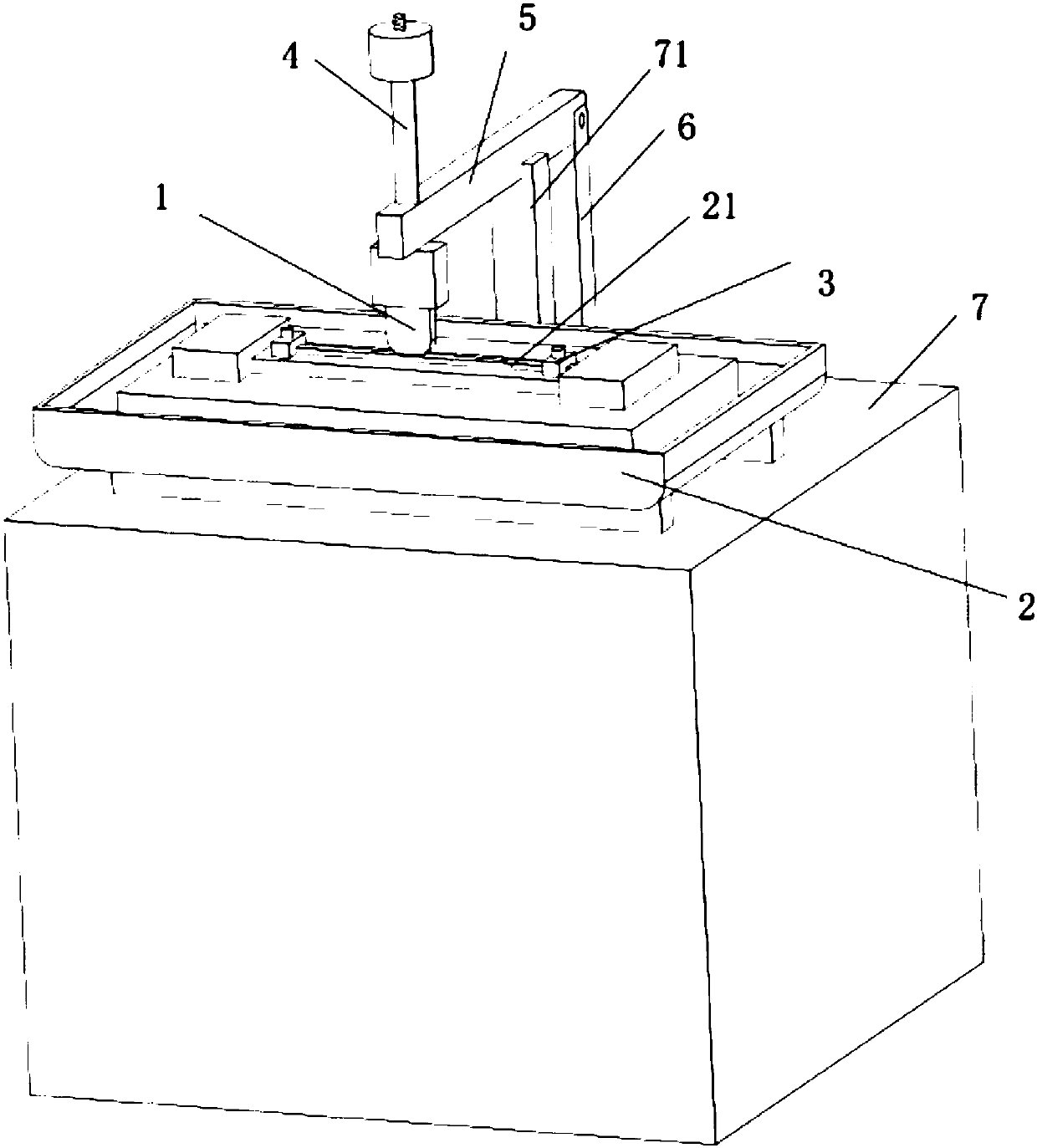
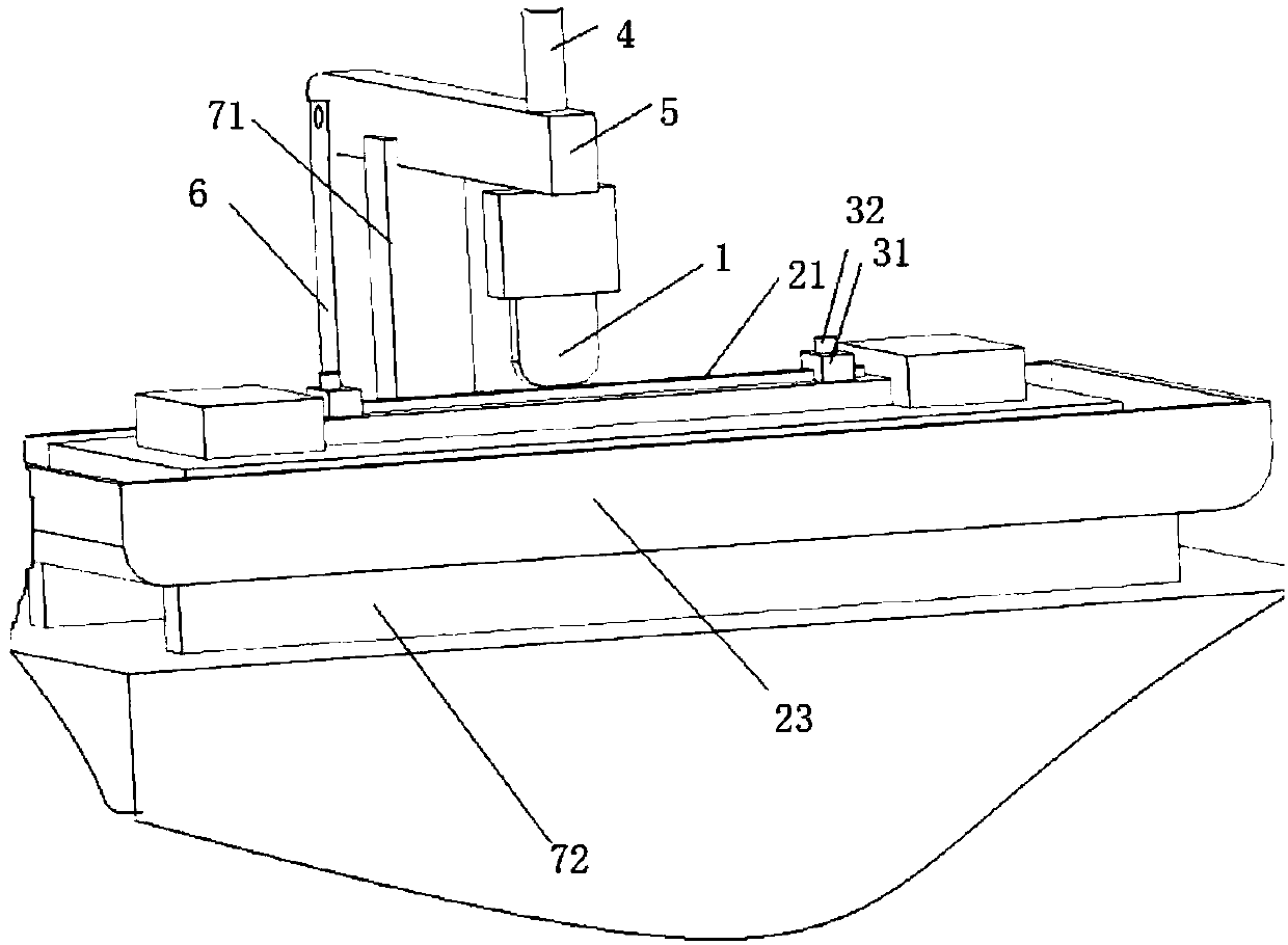
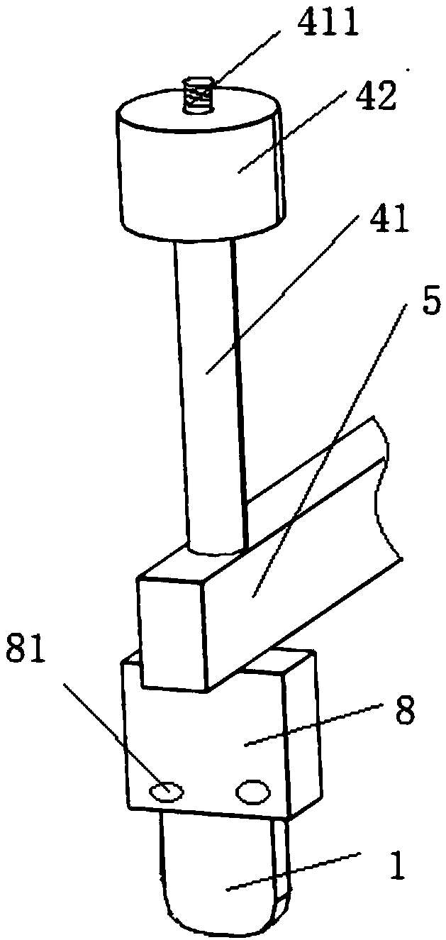
[0028] Such as figure 1 As shown, a test bench for wear resistance of sealing strips includes a friction member 1, a left and right moving mechanism 2, a clamping mechanism 3, a loading mechanism 4 and a friction member beam 5; the friction member 1 is fixedly installed on the friction member On the crossbeam 5, the friction member crossbeam 5 is fixedly connected with the loading mechanism 4; the left and right moving mechanism 2 is provided with an installation position 21 for placing a glass sealing strip, and the clamping mechanism 3 is fixed on the installation At both ends of the position 21, the clamping mechanism 3 fixes the glass sealing strip to the installation position 21; the vertical force generated by the loading mechanism 4 presses down the friction member beam 5, and the friction member 1 and the The glass sealing strip fixed on the installation position 21 is frictionally compressed, and the friction sheet 1 slides relative to the glass sealing strip on the i...
Embodiment 2
[0039] Such as Figure 5 and Figure 6 , Embodiment 2 of the present invention provides a test bench for wear resistance of sealing strips. The difference from Embodiment 1 is that there are two friction member columns 6 in total, and the two friction member columns 6 are respectively located on the friction member beam 5 The two ends of the friction member beam 5 are respectively slidably connected to the corresponding friction member column 6 . The left and right ends of the friction member beam 5 are provided with sliders, and the friction member column 6 is provided with a chute matched with the slider.
[0040]The friction member beam 5 can slide along the friction column 6 under the action of the loading mechanism 4 , so that the friction member 1 on the friction member beam 5 contacts the glass sealing strip on the installation position 21 by pressing down.
Embodiment 3
[0042] Such as Figure 7 , Embodiment 3 of the present invention provides a test bench for the wear resistance of sealing strips. The difference from Embodiment 2 is that the loading mechanism 4 includes a pushing cylinder 44 and a loading mechanism bracket 45 for fixing the pushing cylinder 44. The loading bracket 45 is fixed on the friction member column 6 , and the push rod 441 of the push cylinder 44 is fixedly connected with the friction member beam 5 .
[0043] The friction member beam 5 is pushed to slide along the friction member column 6 by pushing the cylinder 44 , thereby pressing down to make the friction member 1 on the friction member beam 5 contact the glass sealing strip on the installation position 21 .
PUM
 Abstract
Description
Claims
Application Information
 - R&D
- Intellectual Property
- Life Sciences
- Materials
- Tech Scout
- Unparalleled Data Quality
- Higher Quality Content
- 60% Fewer Hallucinations
Browse by: Latest US Patents, China's latest patents, Technical Efficacy Thesaurus, Application Domain, Technology Topic, Popular Technical Reports.
© 2025 PatSnap. All rights reserved.Legal|Privacy policy|Modern Slavery Act Transparency Statement|Sitemap|About US| Contact US: help@patsnap.com


