Clamp for unlocking the locking state of the locking device

A locking device and fixture technology, applied in the direction of manufacturing tools, hand-held tools, etc., can solve the problems of damaging the locking device slideway, easily damaging the locking device and the surface of the circuit board, and the circuit board shaking from side to side, etc. Quality and production efficiency, simplify debugging and maintenance work, and ensure the effect of stable use

Active Publication Date: 2019-06-25
SHAANXI BAOCHENG AVIATION INSTR
View PDF6 Cites 0 Cited by
  • Summary
  • Abstract
  • Description
  • Claims
  • Application Information

AI Technical Summary

Problems solved by technology

When the bolts on the locker are loosened, if Figure 8 As shown, the upper block 8 can be easily loosened with the bolts, but the middle block 9 of the locking device is still tightly fastened between the fixing groove wall and the lower block 10 due to no upward force, even if the bolts are loosened, the middle block 9 cannot be Loose, so that the circuit board cannot be taken out normally
At present, two methods are used to solve this problem: one is to use a flathead screwdriver to pry on the side of the locking device close to the box wall, and then pry on the other side of the locking device close to the box wall, prying back and forth to make the circuit board left and right Shake to loosen block 9 in the locking device
The disadvantages of this method are: 1. The lower part of the circuit board is the plug-in row (pin or hole) that is connected to the base plate (pin or hole). Shaking from side to side can easily cause mechanical damage to the roots of the pins or holes in the plug-in row when shaking. ; 2. Left and right prying will cause irreparable surface damage to the locker and the surface of the box body; the second is to make a hook, hook the lower part of the locker middle block 9 in the locked state, and pull it up to release the lock tight state
The disadvantages of this method are: 1. If the upward force of the hook is too small, the lifting force will not move, and if the force is too large, it will easily damage the locker and the surface of the circuit board; 2. The upward force of the hook cannot be kept in line with the locker. Parallel, damage the slideway of the locker and easily deform the middle block

Method used


Image

  • Clamp for unlocking the locking state of the locking device
  • Clamp for unlocking the locking state of the locking device
  • Clamp for unlocking the locking state of the locking device

Examples


Embodiment Construction

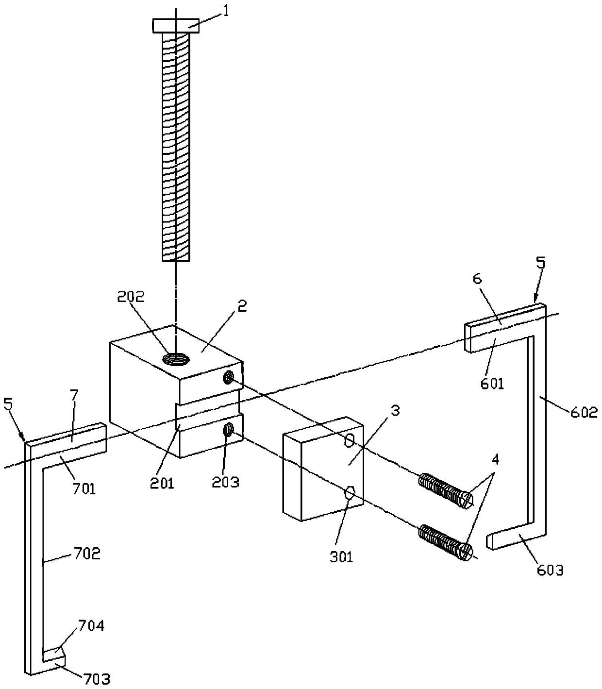
[0022] Attached below Figure 1-6 Embodiments of the present invention are described.

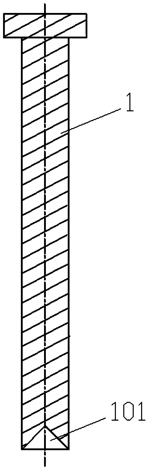
[0023] A jig for releasing the locking state of the locking device, such as figure 1 As shown, it includes a clamp body 2, a lifting screw 1, a baffle plate 3 and a hook plate 5. The vertical thread in the middle of the clamp body 2 is screwed with a lifting screw 1, and the lower end of the lifting screw 1 passes through the clamp body 2 and is used for tightening. Position at the top of the locker bolt head 11. Preferably, the specification of the lifting screw 1 is M4×35, and the clamp body 2 is provided with a threaded hole I 202 screwed with the lifting screw 1 . Specifically, a positioning groove 101 adapted to the top end of the locking device bolt head 11 is formed on the lower end surface of the lifting screw 1, as figure 2 As shown, when the clamp is used to release the locked state of the locker, the positioning groove 101 of the lifting screw 1 is pushed against the bolt he...


PUM


Abstract

Provide a clamp for releasing the locking state of the lock, including the clamp body, lifting screws, baffles and hook plates, the vertical thread in the middle of the clamp body is screwed with the lifting screw whose lower end is tightened on the top of the lock bolt head There is a card slot on one side of the fixture body, the baffle is fixedly connected to the fixture body to block the front opening of the card slot and the openings at both ends of the card slot are open, the upper end of the hook plate is adapted to hook with the card slot and the lower end is connected to the lower part of the middle block of the locker The gap adapter hook is combined with the rotation of the lifting screw to make the fixture body move up slowly and drive the middle block of the locker to loosen to realize the unlocking of the locked state of the locker. The utility model can conveniently and quickly release the locking state of the locking device, effectively solve the problem that the block is stuck in the locking state of the releasing locking device, simplifies the debugging and maintenance work, and reduces the operating procedures during batch debugging and maintenance. Shorten the production cycle and improve work efficiency.

Description

technical field [0001] The invention belongs to the technical field of clamp devices, and in particular relates to a clamp for releasing the locking state of a locking device. Background technique [0002] The circuit board lock (mainly refers to the 201 type locking device) has the characteristics of convenient installation, convenient use, and firm fixation, and is widely used in electronic products for fixing circuit boards. During debugging or maintenance, after the circuit board locker is locked, it is necessary to release the locked state to pull the circuit board out of the fixing slot, such as Figure 7 shown. When the bolts on the locker are loosened, if Figure 8 As shown, the upper block 8 can be easily loosened with the bolts, but the middle block 9 of the locking device is still tightly fastened between the fixing groove wall and the lower block 10 due to no upward force, even if the bolts are loosened, the middle block 9 cannot be If it is loose, the circuit ...

Claims


Application Information

Patent Timeline
Patent Type & Authority Patents(China)
IPC IPC(8): B25B27/00
CPCB25B27/00
Inventor 白强
Owner SHAANXI BAOCHENG AVIATION INSTR
Why Eureka
Try Eureka