Unmanned bridge detection and maintenance device

A bridge detection and bridge technology, applied in the direction of bridges, bridge parts, bridge construction, etc., can solve the problem that the detection device cannot pass through street lights, bridge cables, manual maintenance, etc., to reduce the negative impact of traffic, reduce the structure size, Realize the effect of whole process automation

Active Publication Date: 2018-05-15
CHANGAN UNIV
View PDF6 Cites 8 Cited by
  • Summary
  • Abstract
  • Description
  • Claims
  • Application Information

AI Technical Summary

Problems solved by technology

[0006] In view of the deficiencies in the prior art, the purpose of the present invention is to provide an unmanned bridge detection and maintenance device, which solves the problem that the detection device in the prior art cannot pass through street lamps and bridge cables by itself, and requires manual maintenance

Method used


Image

  • Unmanned bridge detection and maintenance device
  • Unmanned bridge detection and maintenance device
  • Unmanned bridge detection and maintenance device

Examples


Embodiment 1

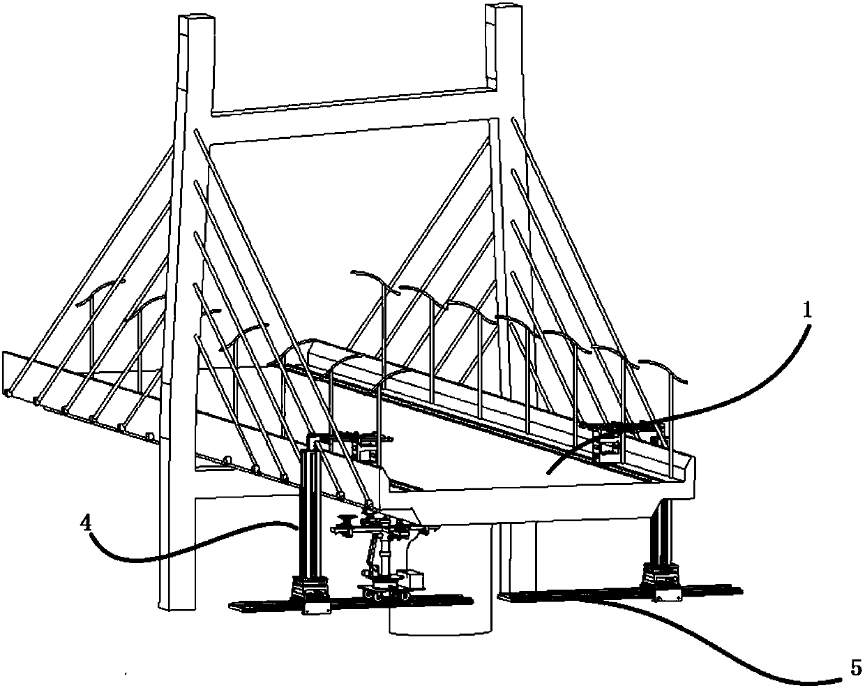
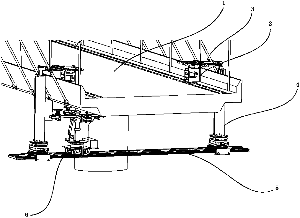
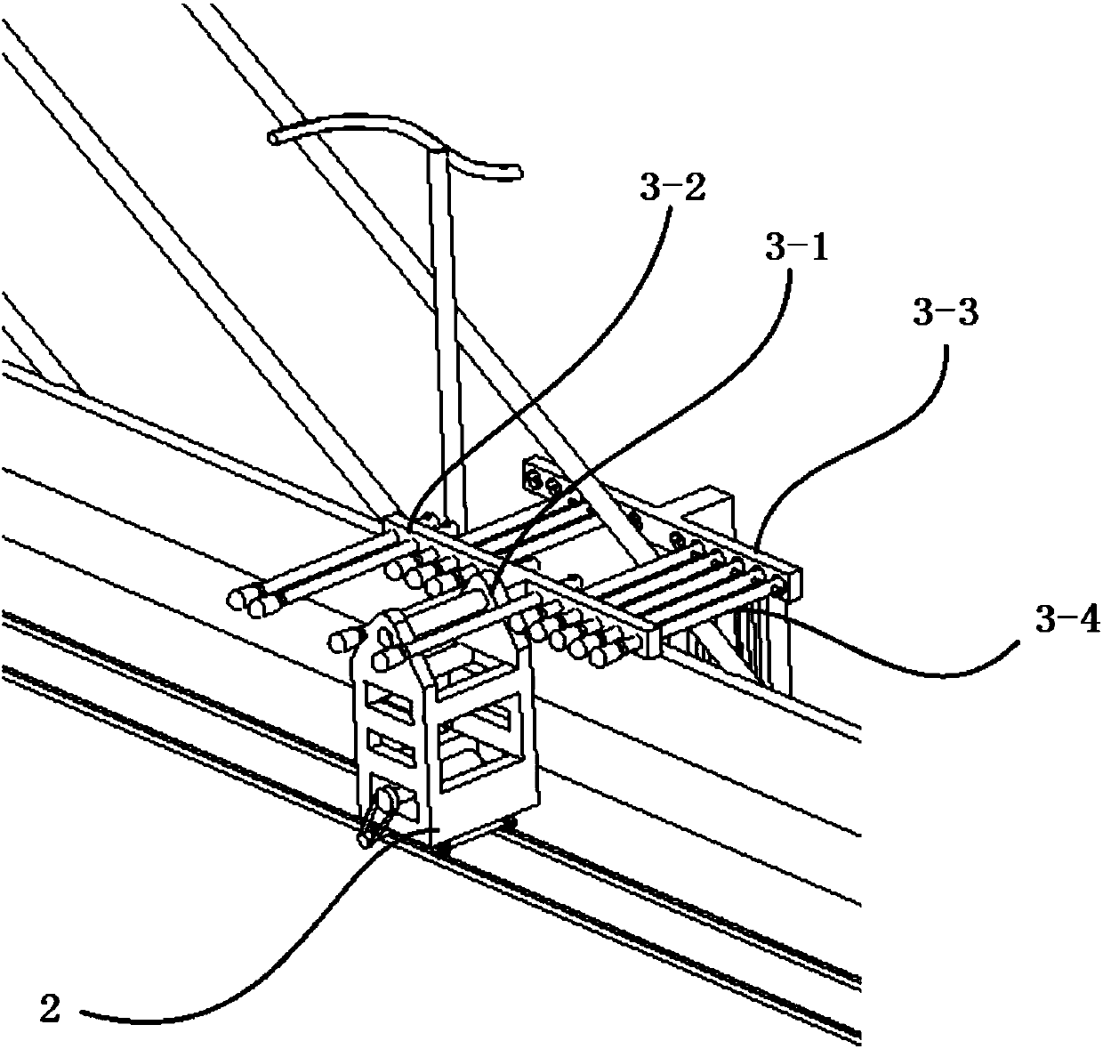
[0048] Such as figure 1 , 2 As shown, the present embodiment provides a bridge detection device, including: a bridge deck running mechanism, including: a drive car 2 is installed longitudinally along the direction of travel on the non-traffic lanes on both sides of the bridge 1, and the drive car 2 can be Walk along the direction of travel of the non-traffic lane; the driving car 2 is provided with a counterweight and a motor, and the motor drives the driving car 2 to advance along the longitudinal direction of the bridge.

[0049] The specific structure of the bridge deck running mechanism in this embodiment may be the structure of the bridge deck running mechanism disclosed in the application number 2016100127105.

[0050] Connecting mechanism, each driving car 2 is connected with a connecting mechanism respectively, and described connecting mechanism comprises transverse connecting arm 3 and vertical connecting arm 4, and one end of described transverse connecting arm 3 is...

Embodiment 2

[0061] On the basis of Embodiment 1, this embodiment provides two guide frames 16-1 vertically on both sides of the round table 7, and a sliding hole is provided at the lower end of the guide frame 16-1, and the sliding hole passes through The bolts are fitted with sliding wheels 16 - 2 cooperating with the side surfaces of the transverse rails 5 . In this way, the pressing force of the guide wheel can be adjusted through the bolts to prevent the working mechanism from turning over.

Embodiment 3

[0063] Such as Figure 5 , this embodiment provides a lifting structure on the basis of Embodiment 1, including a third motor, a second reducer, a crank 8-1, a rocker 8-2, a lifting guide rail 8-3, and a lifting slider 8-4, Lifting guide rail 8-3 is vertically installed on the center of the upper surface of round table 7, and the third motor is connected with one end of crank 8-1 through the second speed reducer, and the other end of crank 8-1 is connected with the end of rocking bar 8-2. One end is connected, the other end of the rocker 8-2 is connected with the lifting slider 8-4, the lifting slider 8-4 is installed on the lifting guide rail 8-3, and the cross-shaped working arm 9 is horizontally arranged on the lifting slider 8-4 on.

[0064] In this embodiment, the third motor and the reducer are installed at the edge of the round table 7, thus forming a crank slider system. Driven by the third motor, the lifting slider slides on the lifting guide rail to realize height a...


PUM


Abstract

The invention provides an unmanned bridge detection and maintenance device. A bearing is arranged at the center of a working walking platform; a circular platform capable of rotating around the bearing is arranged on the bearing; a lifting mechanism coaxial with the circular platform is arranged on the upper surface of the circular platform; a cross-shaped working arm is arranged at the top end ofthe lifting mechanism; a camera is arranged at the center of the cross-shaped working arm; a cutting mechanism, a cleaning mechanism, an adhesive tape pasting mechanism and a filling mechanism are respectively arranged on the cross-shaped working arm; and the cutting mechanism, the cleaning mechanism, the adhesive tape pasting mechanism and the filling mechanism can respectively move along the cross-shaped working arm. The unmanned bridge detection and maintenance device has the advantages that unmanned bridge detection and maintenance operation can be realized and the whole process is automatic.

Description

technical field [0001] The invention belongs to the field of bridges and relates to bridge detection and maintenance, in particular to an unmanned bridge detection and maintenance device. Background technique [0002] With the emergence of a large number of bridges, the problem of bridge aging and damage is gradually increasing. Therefore, it is very important to carry out regular inspection and maintenance of bridges to prolong the service life of bridges and ensure the safety of bridges in service. [0003] In the prior art, there are mainly two types of bridge detection: manual detection and unmanned aerial vehicle detection. At present, the method commonly used at home and abroad is manual inspection and maintenance. In the prior art, the bridge inspection vehicle uses the cantilever to send the truss or the manned basket structure to the bridge, and the technicians inspect the bridge on the truss or the manned basket. Therefore, the structural size of the working devi...

Claims


Application Information

Patent Timeline
Patent Type & Authority Applications(China)
IPC IPC(8): E01D19/10
CPCE01D19/106
Inventor 董忠红赵亮亮车轰王景黄炎
Owner CHANGAN UNIV
Why Eureka
Try Eureka