A modular light-duty high-stiffness passive deployment locking device

A locking device and high rigidity technology, which is applied in transportation and packaging, aerospace equipment, space navigation equipment, etc., to achieve the effect of high locking rigidity and high rotation accuracy

Active Publication Date: 2020-10-09
SHANGHAI SATELLITE ENG INST
View PDF6 Cites 0 Cited by
  • Summary
  • Abstract
  • Description
  • Claims
  • Application Information

AI Technical Summary

Problems solved by technology

Space expandable structures have increasingly high requirements for light weight, high locking rigidity, and efficient modularization of unfolding and locking devices. Existing conventional hinges and other unfolding and locking devices are difficult to meet the above requirements

Method used


Image

  • A modular light-duty high-stiffness passive deployment locking device
  • A modular light-duty high-stiffness passive deployment locking device
  • A modular light-duty high-stiffness passive deployment locking device

Examples


Embodiment Construction

[0026] The present invention will be described in detail below in conjunction with specific embodiments. The following examples will help those skilled in the art to further understand the present invention, but do not limit the present invention in any form. It should be noted that those skilled in the art can make several changes and improvements without departing from the concept of the present invention. These all belong to the protection scope of the present invention.

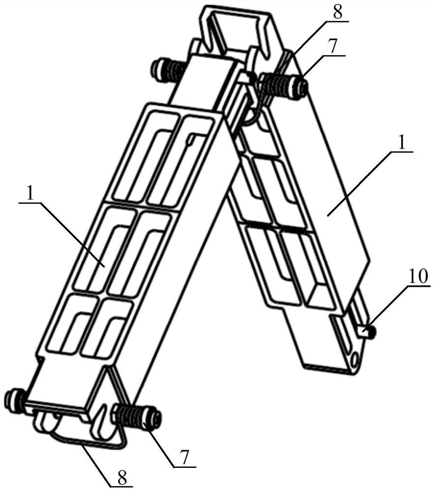
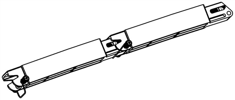
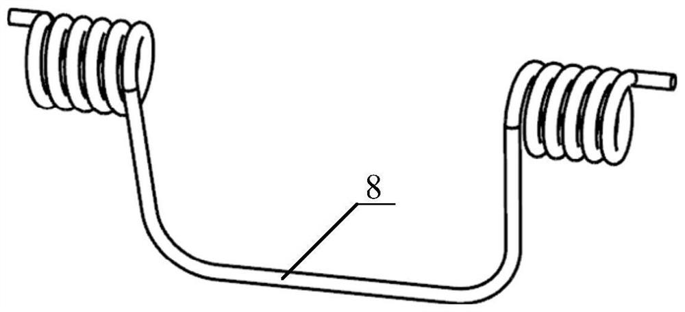
[0027] Figure 1 to Figure 5 As shown, the deployment locking device provided by the present invention includes: deployment arm 1, eccentric adjustment shaft 2, shaft bushing 1 3, shaft bushing 2 4, deployment spring guide shaft 1, deployment spring guide shaft 2 6, deployment spring Spring torque adjustment flange 7, expansion spring 8, pin lock slider 9, pin lock lever 10, pin lock slider thrust spring 11.

[0028] The deployment arm 1 adopts a lightweight design, and combines the design of the deplo...


PUM


Abstract

A modularized light-weight high-rigidity passive deployment locking device comprises deployment arms, eccentric adjustment shafts, first rotary shaft linings, second rotary shaft linings, first deployment spring guide shafts, second deployment spring guide shafts, deployment spring torque adjustment flanges, deployment springs, pin lock sliding blocks, pin lock rods and pin lock sliding block thrust springs. The deployment springs drive the deployment arms to reach locking positions from initial positions, the deployment locking angle is adjusted through the eccentric adjustment shafts, a rotary shaft system is formed by the eccentric adjustment shafts, the first rotary shaft linings, the second rotary shaft linings, the first deployment spring guide shafts, the second deployment spring guide shafts and the deployment springs, the extend-out ends on the two sides of each deployment spring are installed on the corresponding deployment spring torque adjustment flanges, the pin lock sliding blocks and the pin lock rods can integrally conduct linear motion in corresponding piston holes in the deployment arms, the pin lock sliding block thrust springs are adopted to push the pin lock sliding blocks, the pin lock rods enter corresponding pin lock grooves in the deployment arms, and therefore a self-locking structure with certain pre-tightening force is formed. The modularized light-weight high-rigidity passive deployment locking device has the beneficial effects of being high in deployment locking accuracy and rigidity.

Description

technical field [0001] The invention relates to a spacecraft structure and mechanism, in particular to a modular light-duty high-rigidity passive deployment locking device, which is suitable for the field of on-orbit extension and deployment of payloads in spacecraft such as satellites. Background technique [0002] With the development of aerospace technology, space deployable structures have gradually been widely used in the field of aerospace due to their reusability, convenient transportation and storage. Space expandable structures have increasingly high requirements for light weight, high locking rigidity, and high-efficiency modularization of unfolding and locking devices. Existing conventional hinges and other deploying and locking devices are difficult to meet the above requirements. Contents of the invention [0003] Aiming at the defects in the prior art, the object of the present invention is to provide a modular light-duty high-rigidity passive deployment lock...

Claims


Application Information

Patent Timeline
Patent Type & Authority Patents(China)
IPC IPC(8): B64G1/22
CPCB64G1/22B64G1/222
Inventor 杨铭波赵枝凯王智磊杜三虎申军烽袁野
Owner SHANGHAI SATELLITE ENG INST
Why Eureka
Try Eureka