Tubular implant device for preventing electric pole from being frozen to be bulged and tilting, manufacturing method thereof and rod standing method based on tubular implant device

A technology for implanting devices and electric poles, which is applied in the field of electric pole foundations, can solve problems such as the reduction of power supply reliability, and achieve the effect of long safe operation time and saving maintenance funds

Active Publication Date: 2018-05-18
国网黑龙江省电力有限公司齐齐哈尔供电公司 +1
View PDF4 Cites 0 Cited by
  • Summary
  • Abstract
  • Description
  • Claims
  • Application Information

AI Technical Summary

Problems solved by technology

[0003] The object of the present invention is to solve the problem of the power supply reliability being reduced due to the inclination of the electric pole caused by the freezing of the ground, and to provide a tubular implantation device for preventing the inclination of the electric pole from the freezing of the ground, its manufacturing method and a vertical pole based on the device method

Method used


Image

  • Tubular implant device for preventing electric pole from being frozen to be bulged and tilting, manufacturing method thereof and rod standing method based on tubular implant device
  • Tubular implant device for preventing electric pole from being frozen to be bulged and tilting, manufacturing method thereof and rod standing method based on tubular implant device
  • Tubular implant device for preventing electric pole from being frozen to be bulged and tilting, manufacturing method thereof and rod standing method based on tubular implant device

Examples


specific Embodiment approach 1

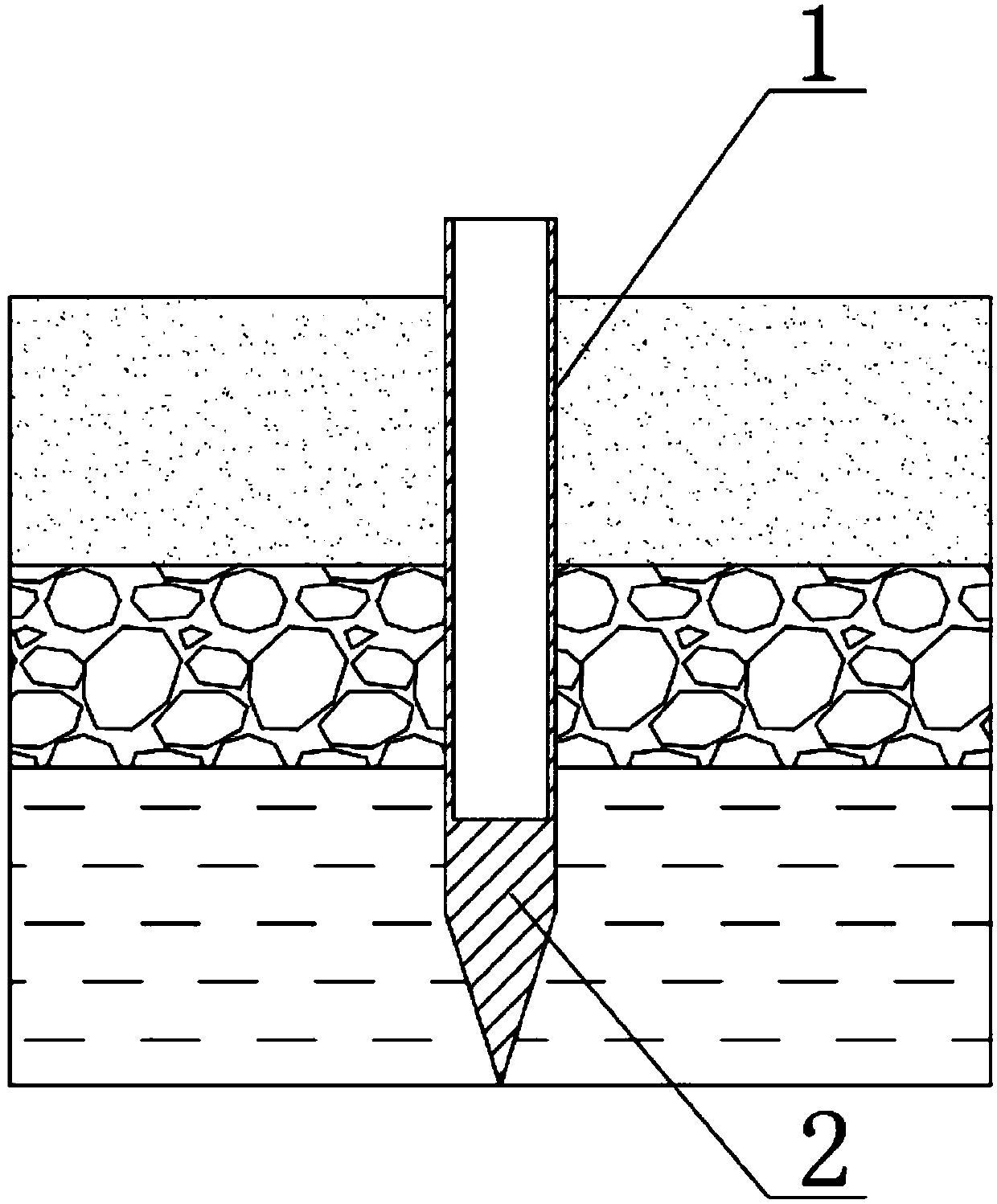
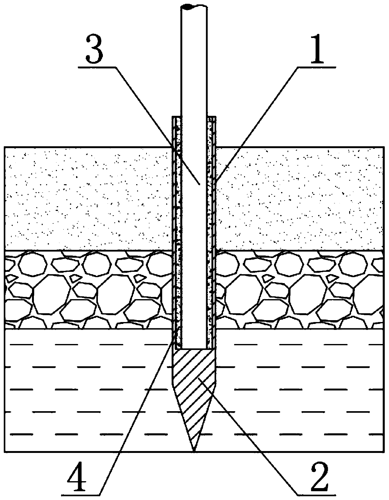
[0019] A tubular implant device for preventing the inclination of the electric pole freezing drum, comprising a casing 1 and a tapered part 2, the tapered part 2 is coaxially fixed on the bottom of the casing 1, and the tubular implant for preventing the inclination of the electric pole freezing drum The lowest point of the entry device is set at 2.8m~3.3m below the ground surface.

[0020] In this specific embodiment, the casing 1 and the tapered portion 2 are integrally provided. The tubular implant device for preventing the tilting of the pole freezing drum should be located 1.0m to 1.5m below the permafrost layer, and the distance below the ground surface is determined according to the thickness of the permafrost layer. m, so the lowest point of the device is located at a depth of 2.8m to 3.3m below the surface.

specific Embodiment approach 2

[0021] like figure 1 As shown, the difference between the second embodiment and the first embodiment is that the bottom surface of the tapered portion 2 is greater than or equal to the cross section of the sleeve 1 . The purpose of setting the tapered part 2 is to make use of the shape characteristics of the tapered part 2, so that the whole device can be easily driven into the ground below the surface. Therefore, the bottom surface of the tapered part 2 is required to be greater than or equal to the cross section of the casing 1. If If it is smaller than that, the effect will not be achieved, and even the casing 1 may be damaged.

specific Embodiment approach 3

[0022] like figure 1 As shown, the wall thickness of the casing 1 is 4mm-6mm, the inner diameter is 230mm-500mm, and the height is 2.5m-2.8m; the height of the tapered part 2 is 0.6m-1.0m.

[0023] The above parameters are preferably casing 1 with a wall thickness of 5mm and a height of 2.65m. The electric pole adopts the concrete electric pole specification stipulated by the current national standard. Therefore, the inner diameter of the casing 1 is added to the diameter of the electric pole by 100mm, and the height of the tapered part 2 It is 0.65m.


PUM


Abstract

The invention discloses a tubular implant device for preventing an electric pole from being frozen to be bulged and tilting, a manufacturing method thereof and a rod standing method based on the tubular implant device, and relates to a foundation used for a vertical rod, a tower or a chimney and a manufacturing method and using method thereof, in particular to the field of electric pole foundations. The aim is to solve the problem that power supply reliability is reduced due to tilting of the electric pole caused by the land being frozen to be bulged. The tubular implant device for preventingthe electric pole from being frozen to be bulged and tilting comprises a sleeve, the lowest point of the tubular implant device for preventing the electric pole from being frozen to be bulged and tilting is arranged at the position below a frozen soil layer, wherein the distance from the position to the frozen soil layer is 1.0-1.5 m, and the bottom of the sleeve is coaxially and fixedly providedwith a tapered tip part. The tubular implant device has the beneficial effects that the situation that the power supply reliability is reduced due to tilting of the electric pole caused by the land being frozen to be bulged seasonally and molten under the situation that large construction cannot be conducted at a wetland protected area in the northeast.

Description

technical field [0001] The invention relates to a foundation for a pole, a tower or a chimney, a manufacturing method and a use method thereof, in particular to the field of a pole foundation. Background technique [0002] The part of the pole buried in the ground is the pole foundation. According to the requirements of the typical design scheme of the distribution network of the State Grid Corporation of China, the cement pole foundation type is to set up reinforced concrete prefabricated parts underground, stone processing prefabricated parts, and cast cement on site. , but the cost of the above method is too high, and the basic type used under low temperature conditions is not suitable for the climate and soil conditions of the wetland areas in Northeast China. In the wetland area of ​​Northeast China, when the temperature drops in winter, the soil with high water content starts to freeze and bulge, pulling up together with the pole; when the temperature rises in spring, ...

Claims


Application Information

Patent Timeline
Patent Type & Authority Applications(China)
IPC IPC(8): E04H12/22
CPCE04H12/2215
Inventor 李学忠沈宏伟董勇民王春江佟晓明郑声宇崔继浩孙毅孙杰赵立业
Owner 国网黑龙江省电力有限公司齐齐哈尔供电公司
Why Eureka
Try Eureka