Automatic injection mold

An automatic injection molding and mold technology, applied in the field of mold design, can solve the problems of increased production cost, low yield rate and reduced cooling effect, and achieve the effect of saving production cost and improving production efficiency

Inactive Publication Date: 2018-05-22
余姚市宏硕模具制造有限公司
View PDF0 Cites 0 Cited by
  • Summary
  • Abstract
  • Description
  • Claims
  • Application Information

AI Technical Summary

Problems solved by technology

[0002] In traditional injection molds, the return spring is used as the push-out mechanism to push the molded product out of the mold; when it is working, when the injection head is moved away, the push-out mechanism pushes the product out immediately. Due to the continuous work of the mold, the cooling effect is reduced. Some products are pushed out before being cooled and formed, resulting in product deformation and low yield
Moreover, the traditional injection mold can only meet the injection molding of one size product. If other products are used, the injection mold will not be applicable, resulting in an increase in production costs.

Method used


Image

  • Automatic injection mold

Examples


Embodiment

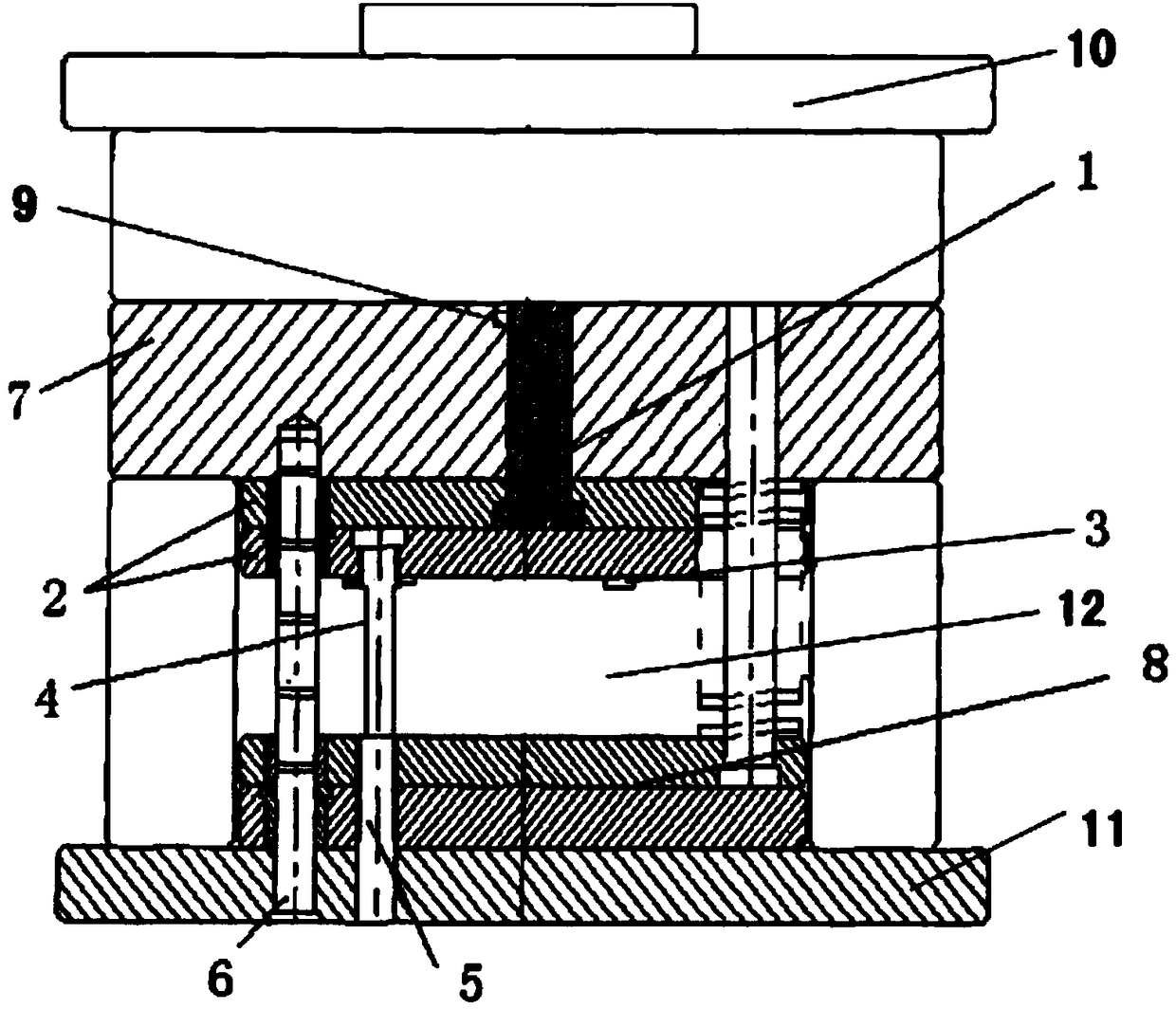
[0018] Example: see figure 1 , the present embodiment provides an automatic injection mold, which includes an upper mold 10 and a lower mold 11, a supporting plate 7 is provided between the upper mold 10 and the lower mold 11, and an automatic ejection mechanism is provided in the lower mold 11, Guide post 6, cavity 12 and face needle plate 8.

[0019] The automatic push-out mechanism includes a cylinder chamber 5 , a push rod 4 , a floating core 1 and a floating plate 2 connected to each other.

[0020] The cylinder chamber 5 is fixed at the lower die 11 of the mold, and the push rod 4 is fixed at the bottom of the floating plate 2 and connected with the cylinder chamber 5 .

[0021] The floating core 1 is fixed on the upper part of the floating plate 2 and is located in the cavity.

[0022] It also includes an infrared distance sensor 3 and a temperature sensor 9 .

[0023] The infrared distance sensor 3 is located at the bottom of the floating plate 2 .

[0024] When in...


PUM


Abstract

The invention discloses an automatic injection mold. The automatic injection mold comprises an upper mold and a lower mold, and is characterized in that a support plate is arranged between the upper mold and the lower mold; an automatic pushing mechanism, a guide column, a cavity and a surface needle plate are arranged in the lower mold; and the automatic pushing mechanism comprises a cylinder chamber, a pushing rod, a floating core body and a floating plate connected with each other. The automatic injection mold further comprises an infrared distance sensor and a temperature sensor. The automatic injection mold has the following beneficial effects: through arrangement of a cylinder and a cylinder linkage piece and cooperation with a sensor for use, after a mold is molded, the injection mold can automatically push the molded product outside, so that the production efficiency is greatly improved; and the distance sensor is adopted to adjust the distance of the core body moving in a molding cavity to adapt to injection molding products with different sizes so as to save the production cost.

Description

technical field [0001] The invention relates to the field of mold design, in particular to an automatic injection mold. Background technique [0002] In traditional injection molds, the return spring is used as the push-out mechanism to push the molded product out of the mold; when it is working, when the injection head is moved away, the push-out mechanism pushes the product out immediately. Due to the continuous work of the mold, the cooling effect is reduced. Some products are pushed out before being cooled and formed, resulting in product deformation and low yield. Moreover, the traditional injection mold can only meet the injection molding of one size product. If other products are replaced, the injection mold will not be suitable, resulting in an increase in production costs. Contents of the invention [0003] The purpose of the present invention is to provide an automatic injection mold for the deficiencies of the prior art. By setting the cylinder and the cylinder...

Claims


Application Information

Patent Timeline
IPC IPC(8): B29C45/40B29C45/26
CPCB29C45/4005B29C45/2602
Inventor 张新鹏
Owner 余姚市宏硕模具制造有限公司
Why Eureka
Try Eureka