
Transformer station communication optical cable connector

A technology for optical cable connectors and substations, applied in the direction of light guides, optics, instruments, etc., can solve problems such as large impact, long construction period of optical cable construction, and weak plugging of plugging devices, so as to solve the problem of not firm plugging and strengthen stability The effect of sex and hermeticity

Inactive Publication Date: 2018-05-25
STATE GRID SHANDONG ELECTRIC POWER COMPANY WEIFANG POWER SUPPLY +1
View PDF7 Cites 3 Cited by
  • Summary
  • Abstract
  • Description
  • Claims
  • Application Information

AI Technical Summary

Problems solved by technology

[0003] The invention provides a communication optical cable connector in a substation, which realizes on-site optical cable plug-in construction by using a generalized plug-in optical cable and a connecting plug-in, and has obvious economical efficiency and strong practicability; it solves the problem of on-site welding construction of optical cables Affected by people and the environment, the construction period of the optical cable is long, and the on-site welding-free construction of the optical cable is truly realized. The invention strengthens the stability and airtightness of the plug-in joint, and solves the problem that the traditional plug-in device is not firmly plugged in. Affected by ambient light, etc.

Method used


Image

  • Transformer station communication optical cable connector
  • Transformer station communication optical cable connector
  • Transformer station communication optical cable connector

Examples


Embodiment Construction

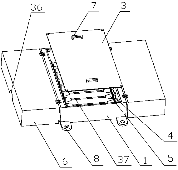
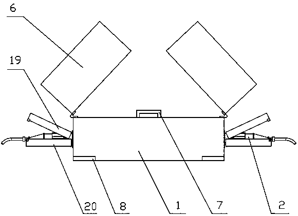
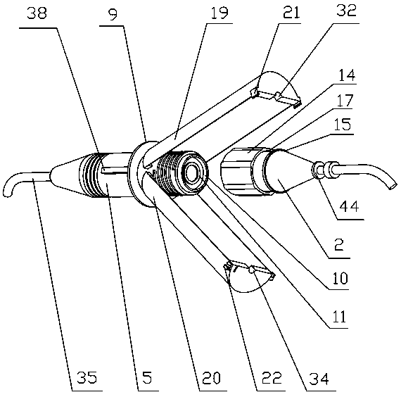
[0032] The characteristics of a substation communication optical cable connector as shown in the figure include: a connection box 1, a plug 2; a box cover 3 is provided on the connection box 1, and the box cover 3 and the connection box 1 are connected by screws at corresponding positions, and the connection box The side wall of 1 is provided with the first through hole 4, and the socket 5 that is plugged and matched with the through hole is installed in the first through hole 4, and the two ends of the socket 5 are provided with threads, and the corresponding two sides of the connection box 1 The socket 5 is connected by an optical fiber 37; the plug 2 corresponds to the socket 5 and the two are plug-fitted. 10 is the first slot 12 that slides and fits, and the optical fiber core 13 on the end face of the plug 2 corresponds to the optical fiber core 13 on the end face of the socket 5; The second limit block 15 and the third limit block 16 connected to the side of the plug 2, ...


PUM


Abstract

The invention discloses a transformer station communication optical cable connector. The transformer station communication optical cable connector comprises a connection box and plugs, wherein the connection box is provided with a box cover, the box cover and the connection box are connected through a screw at the corresponding position, a side wall of the connection box is provided with a first through hole, the first through hole is internally equipped with jacks in plugging matching with the through hole, two end side surfaces of the jacks are provided with thread, the corresponding jacks at two sides of the connection box are connected through fiber, the plugs and the jacks correspond to each other and are in plugging matching, a side surface of the jacks is provided with an upper shield and a lower cover which are respectively in hinge matching with the jacks, the upper shield is provided with a fixing block fixedly connected with a side wall of the upper shield, the fixing blockis a hook structure, and the lower cover is provided with a clamping mechanism in clamping matching with the fixing block. The transformer station communication optical cable connector is advantaged in that stability and sealingness of the plugging portion are enhanced, and a problem that a traditional plugging connector is not firmly connected and affected by ambient light is solved.

Description

technical field [0001] The invention relates to a communication optical cable connector of a substation. technical background [0002] At present, the connection method of optical cables in smart substations is: "on-site fusion splicing + ODF optical fiber distribution frame + optical fiber jumper" connection method. The fusion splicing process is complicated, and the workers for splicing optical fibers need to be recruited separately, increasing the management process. The operation level of personnel is uneven; optical fiber fusion is affected by environmental temperature, humidity and dust; fusion is time-consuming and laborious, and the construction period and debugging period of fusion splicing are long, which affects the progress of the project; optical fiber fusion splicing Points require special protection to prevent breakage. If the traditional plug-in is used, the firmness is low. The traditional plug-in device has poor protection for the plug-in point, and it is ...

Claims


Application Information

Patent Timeline
IPC IPC(8): G02B6/38
CPCG02B6/3825G02B6/3831G02B6/3851G02B6/3881
Inventor 王明轩张双莹吴强晋飞管桦曹凯朱晓耕张超刘晓亮孙继磊魏玉苓孙守鑫王秉煜
Owner STATE GRID SHANDONG ELECTRIC POWER COMPANY WEIFANG POWER SUPPLY
Learn More